Pressure sensor

a pressure sensor and pressure sensor technology, applied in the field of pressure sensors, can solve the problems of difficult control of pressure thresholds, inability to accurately measure applied pressure over a sufficiently wide range, etc., and achieve the effect of reliable pressure or force measurement results

Inactive Publication Date: 2010-08-10
INGO MAYER GMBH & CO KG
View PDF18 Cites 58 Cited by
  • Summary
  • Abstract
  • Description
  • Claims
  • Application Information

AI Technical Summary

Benefits of technology

[0007]It is an object of the invention to provide a pressure sensor which is compatible with textile production processes such as weaving, knitting, warp knitting or sewing and which gives precise and reliable pressure or force measurement results.
[0009]The pressure sensor of the invention has the advantage that the electric response on the applied pressure depends primarily on the response of the pressure sensitive layer in the multilayer thread, rather than on the contact resistance between the conductive threads. Thus, the sensor can give precise and reliable pressure or force measurement results.

Problems solved by technology

It has been found that the textile pressure sensors known in the art do not allow precise measurement of an applied pressure over a sufficiently wide range.
Moreover, the pressure threshold is difficult to control and depends on hysteresis effects.

Method used


Image

  • Pressure sensor
  • Pressure sensor
  • Pressure sensor

Examples


first embodiment

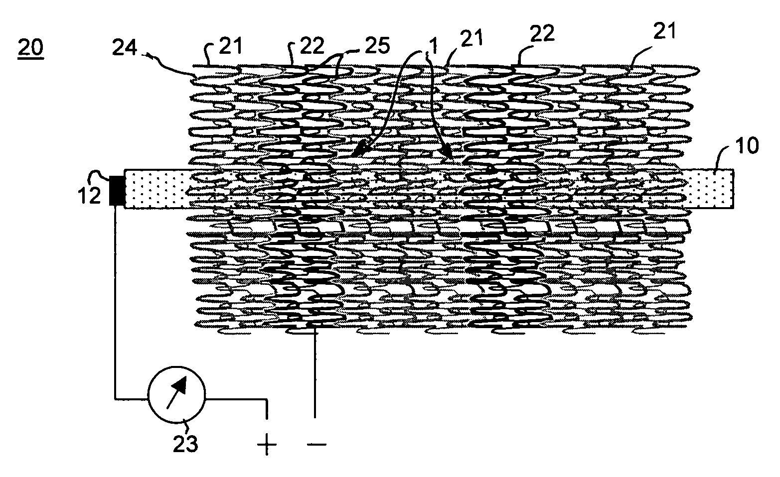
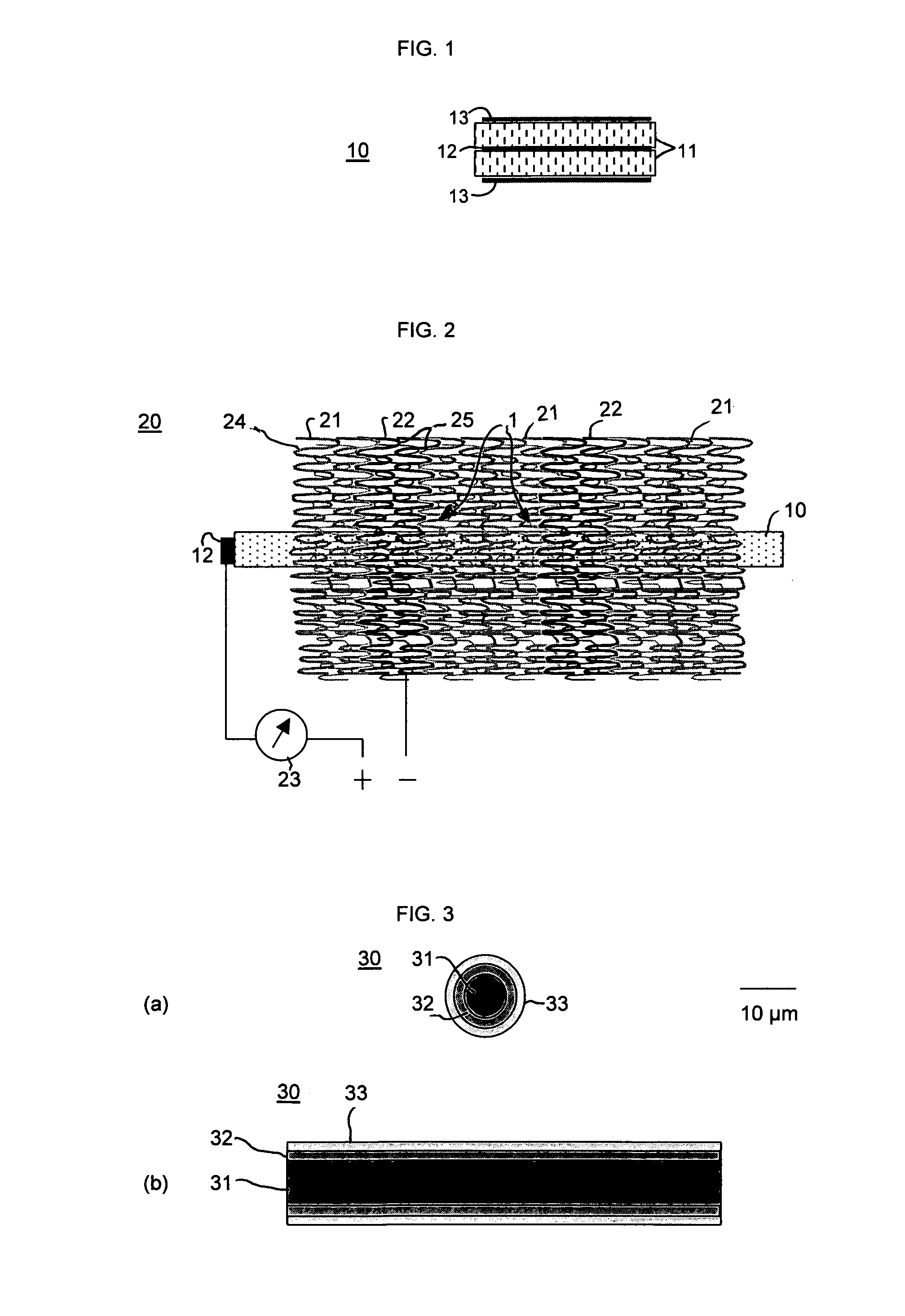
[0019]A textile pressure sensor in accordance with the invention is shown in FIGS. 1, and 2. This sensor includes a multilayer thread being a fine strip of laminated film 10, incorporated into a fabric 20.

[0020]FIG. 1 shows a cross-sectional view of the laminated film 10. The laminated film 10 comprises a core made of an electrically conductive layer 12. Both surfaces of the conductive layer 12 are covered by pressure sensitive layers 11.

[0021]The outer surfaces of the pressure sensitive layers 11 are covered by electrically conductive electrode layers 13. The pressure sensitive layers 11 are made of an electrically conductive elastic material that shows a pressure-dependent resistance between the conductive layer 12 and the electrode layers 13. The material may be a conductive polymer like polyaniline. Another preferred material is an elastic insulator such as silicone, including conductive filler particles such as carbon black particles. As an alternative, the pressure sensitive l...

second embodiment

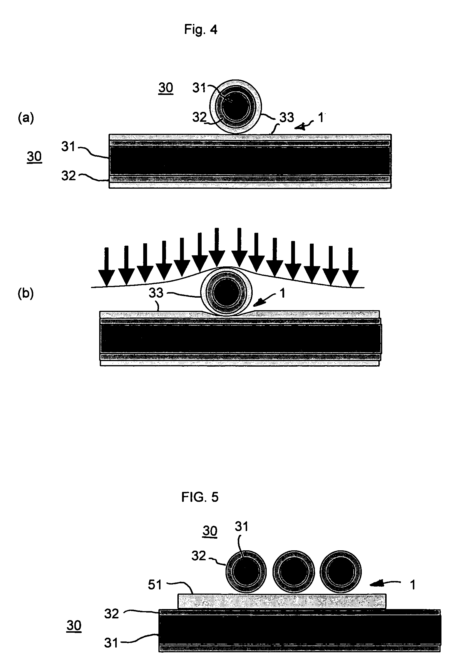
[0028]FIG. 6 shows the structure of the multilayer thread 30 of the second embodiment in more detail. The polymer fiber 31 forming the core of the thread comprises a multitude of filaments 34. The core is coated by the conductive coating 32 made of a good conductor, preferably a metal such as aluminum, copper or, preferable, silver. The conductive coating 32 is, in turn, covered by a pressure sensitive coating 33 made of an elastic material having an electric resistivity in between that of a good conductor such as a metal, and that of an insulator. It may be made of a conductive polymer such as polyaniline, or of an insulating polymer or elastomer containing conductive filler particles, such as silicone containing carbon black particles. Thus, the electric resistance measured in radial direction of the thread 30 between the conductive coating 32 and the outer surface of the pressure sensitive coating 33 depends on the thickness of the pressure sensitive coating 33 and thus on the de...

fourth embodiment

[0029]FIG. 7 shows a sock 70 as an example of a garment incorporating a pressure sensor in accordance with the invention. The sock 70 is made of a knitted fabric mainly consisting of insulating yarn such as cotton, wool or synthetic fiber. Incorporated into the fabric are filler threads extending in longitudinal direction spaced apart and parallel to each other. The filler threads are made of the multilayer threads 30 shown in FIGS. 3 and 6. Further incorporated into the fabric are warp threads made of conductive: threads 25 which extend in generally horizontal, direction of the sock along spaced apart conductive zones 22 in the way as shown in FIG. 2. Thus, the fabric of the sock 70 resembles that of FIG. 2 except that the strip of laminated film 10 of the FIG. 2 embodiment is replaced by a multilayer thread 30 of the FIG. 3 embodiment.

[0030]When the conductive threads 25 and the multilayer threads 30 are connected to an electronic circuit as disclosed in DE 103 14 211 A1, the circ...


PUM

PropertyMeasurementUnit
pressureaaaaaaaaaa
electric characteristicaaaaaaaaaa
pressure sensitiveaaaaaaaaaa

Abstract

The invention relates to a pressure sensor which can be incorporated into textile products. The pressure sensor includes a multilayer thread having a pressure sensitive layer exhibiting a pressure-dependent electrical resistance, and a conductive layer in contact with the pressure sensitive layer. Further, the sensor includes conductive threads in contact with the multilayer thread.

Description

CROSS-REFERENCE TO RELATED APPLICATIONS[0001]This application is a National Phase Application based upon and claiming the benefit of priority to PCT / EP2006 / 011250, filed on Nov. 23, 2006 which is based upon and claims the benefit of priority to German Application 10 2005 055 842.9, filed on Nov. 23, 2005, the contents of which are incorporated herein by reference.BACKGROUND OF THE INVENTION[0002]The invention relates to a pressure sensor and a textile product including the sensor.[0003]DE 10314211 A1 discloses a sock having a pressure sensor to measure the pressure distribution around the foot of, e.g., a diabetic patient. The measurement is used in the adaptation of a shoe to the patient's foot so as to avoid pressure peaks which would lead to tissue damage (diabetic foot syndrome). The sock includes a matrix of metallic fibers incorporated into the fabric of the sock. The metallic fibers are connected to an electronic circuit which computes the pressure distribution from the elect...

Claims


Application Information

Patent Timeline
Patent Type & Authority Patents(United States)
IPC IPC(8): G01L1/00
CPCA61B5/1036A61B5/6804A61B5/6807A61B5/6887D04B1/16G01L1/205A61B5/6892A61B5/1074D10B2403/02431A61B2562/0247A61B2562/046A61B2562/164
Inventor VON LILIENFELD-TOAL, HERMANNASFOUR, JEAN-MICHEL
Owner INGO MAYER GMBH & CO KG
Why Eureka
Try Eureka