
Pneumatic tire with electrically conductive helical path

Inactive Publication Date: 2010-08-10
SUMITOMO RUBBER IND LTD
View PDF13 Cites 1 Cited by
  • Summary
  • Abstract
  • Description
  • Claims
  • Application Information

AI Technical Summary

Benefits of technology

[0004]It is therefore, an object of the present invention to provide a pneumatic tire in which, even if almost-insulative high-performance rubbers such as silica-rich compounds are used as the sidewall rubber, the entirety of the

Problems solved by technology

In the case of the silica-rich rubber compounds, however, the electric res

Method used


Image

  • Pneumatic tire with electrically conductive helical path
  • Pneumatic tire with electrically conductive helical path
  • Pneumatic tire with electrically conductive helical path

Examples


Example

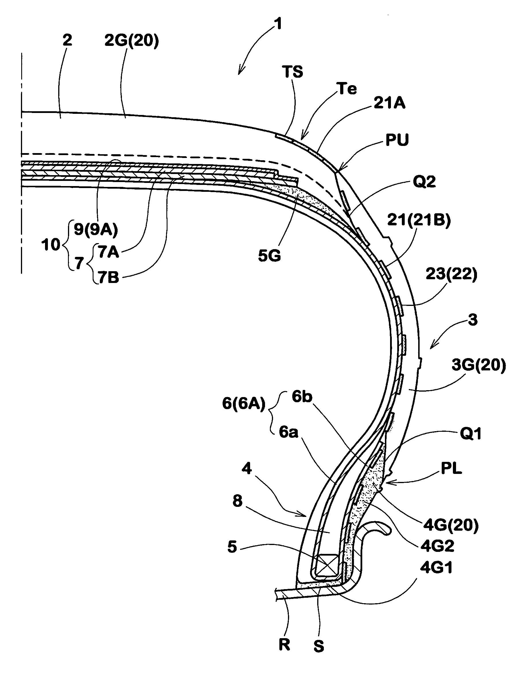
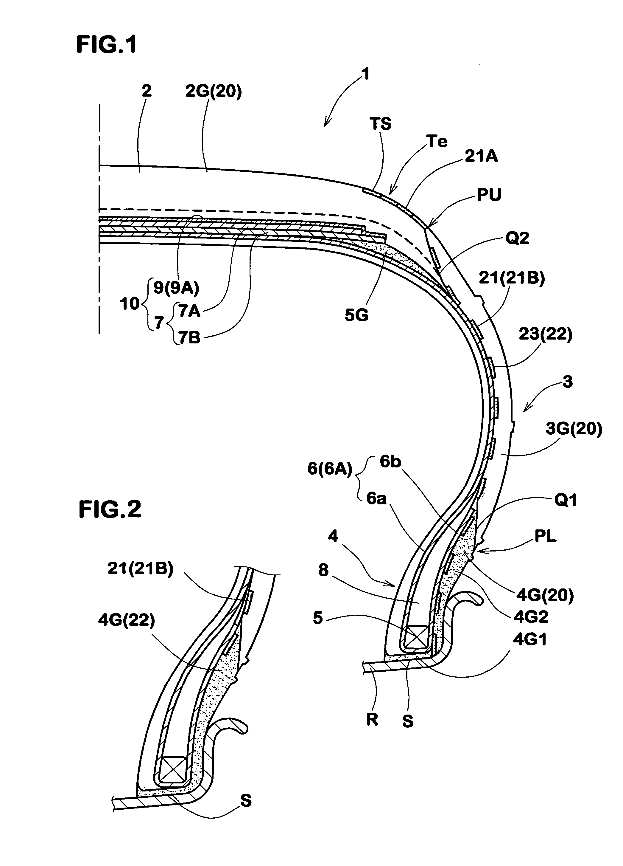
[0020]In the drawings, pneumatic tire 1 according to the present invention comprises a tread portion 2, a pair of sidewall portions 3, and a pair of axially spaced bead portions 4. In FIG. 1, there is shown the pneumatic tire 1 mounted on a wheel rim R and inflated to a normal pressure. As usual, to reinforce the tire, a carcass 6 is disposed to extend between the bead portions 4 through the tread portion 2 and sidewall portions 3. A bead core 5 is disposed in each of the bead portions 4. A belt 10 is disposed in the tread portion 2.

[0021]Further, various rubber components are disposed, which include:

[0022]a tread rubber 2G disposed radially outside the carcass 6 to define a part of the tire outer surface in the tread portion;

[0023]a sidewall rubber 3G disposed axially outside the carcass 6 to define a part of the tire outer surface in each of the sidewall portions: and

[0024]a clinch rubber 4G disposed in each of the bead portions to define an axially outer surface and bottom surfac...


PUM


Abstract

A pneumatic tire is provided with an electrically conductive path extending continuously from a position in the rim contacting surface to a position in the ground contacting surface through a sidewall portion, wherein a sidewall rubber is a high-performance rubber compound and almost-insulative, having a volume resistivity of not less than 1×10^8 ohm cm. The electrically conductive path includes a helical path made of an electrically conductive rubber having a volume resistivity of not more than 1×10^7 ohm cm. The helical path is disposed axially inside the sidewall rubber and extends spirally around the tire rotational axis. Preferably, the tread rubber, clinch rubber and carcass topping rubber are also almost-insulative high-performance rubber compounds.

Description

BACKGROUND OF THE INVENTIONField of the Invention[0001]The present invention relates to a pneumatic tire provided with an electrically conductive path for discharging static electricity.DESCRIPTION OF RELATED ART[0002]In order to improve the rolling resistance and wet grip performance of a pneumatic tire, the use of a silica-rich rubber compound has been proposed, for example in Japanese patent application publication JP-A-09-071112. In the case of the silica-rich rubber compounds, however, the electric resistance of the vulcanized rubber becomes very high, and almost insulative. In this proposition, therefore, in order to discharge static electricity to the ground through the tread portion, as shown in FIG. 8, the tread rubber (a) is provided with a double layered structure comprising an outer layer (b) of a silica-rich compound and an inner conductive layer (c) of a carbon-rich compound. And the inner conductive layer (c) is provided with grounding parts (c1) penetrating the outer...

Claims


Application Information

Patent Timeline
IPC IPC(8): B60C13/00B60C19/08B29D30/60B29D30/72
CPCB60C19/08B29D2030/526Y10S152/02Y10T152/10828
Inventor NOBUCHIKA, HIDEOUCHIDA, MAMORUMIKI, YOUJIROUYAMAMORI, SYUICHI
Owner SUMITOMO RUBBER IND LTD
Features
  • Generate Ideas
  • Intellectual Property
  • Life Sciences
  • Materials
  • Tech Scout
  • Unparalleled Data Quality
  • Higher Quality Content
  • 60% Fewer Hallucinations
Learn More