
Vapor injection system for a scroll compressor

a scroll compressor and vapor injection technology, applied in the direction of machines/engines, liquid fuel engines, positive displacement liquid engines, etc., can solve the problems of unnecessarily consuming energy and dead volume, and achieve the effect of increasing operating efficiency and capacity and unnecessarily consuming energy

Active Publication Date: 2010-08-10
COPELAND LP
View PDF27 Cites 46 Cited by
  • Summary
  • Abstract
  • Description
  • Claims
  • Application Information

AI Technical Summary

Benefits of technology

The solution effectively reduces energy wastage by minimizing dead volume and optimizing the operation of the vapor injection system, enhancing the overall efficiency and capacity of the compressor.

Problems solved by technology

During operation, passages between the vapor injection system and the compression mechanism may create dead volume that is compressed, consuming energy unnecessarily.

Method used


Image

  • Vapor injection system for a scroll compressor
  • Vapor injection system for a scroll compressor
  • Vapor injection system for a scroll compressor

Examples


Embodiment Construction

[0012]The following description is merely exemplary in nature and is not intended to limit the present teachings, application, or uses.

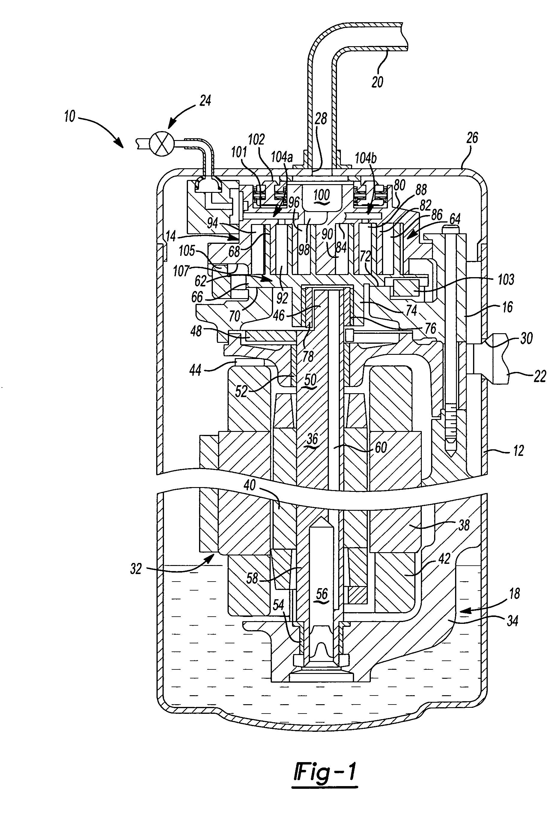
[0013]The present teachings are suitable for incorporation in many different types of scroll and rotary compressors, including hermetic machines, open drive machines and non-hermetic machines. For exemplary purposes, a hermetic scroll refrigerant motor-compressor 10 of the low-side type, i.e., where the motor and compressor are cooled by suction gas in the hermetic shell, as illustrated in the vertical section shown in FIG. 1, is described herein.

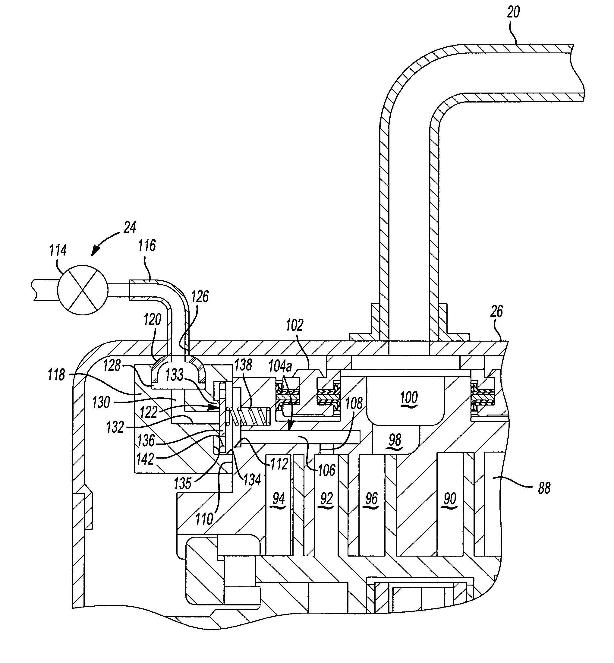
[0014]With reference to FIGS. 1, 3, 5, and 6, compressor 10 may include a cylindrical hermetic shell 12, a compression mechanism 14, a main bearing housing 16, a motor assembly 18, a refrigerant discharge fitting 20, a suction gas inlet fitting 22, and a vapor injection system 24. The hermetic shell 12 may house the compression mechanism 14, main bearing housing 16, and motor assembly 18. Shell 12 may includ...


PUM


Abstract

A compressor may include a shell, a compression mechanism, a motor, and a vapor injection system. The compression mechanism may be contained within in the shell and include a non-orbiting scroll axially displaceably mounted to the shell. The non-orbiting scroll may have an exterior portion, an interior portion, and a vapor injection passage extending therethrough from the exterior portion to the interior portion. The motor may be contained within the shell and may be drivingly coupled to the compression mechanism. The vapor injection system may include a vapor injection device, a vapor injection fitting, and a vapor injection valve. The vapor injection fitting may be in communication with the vapor injection device and the vapor injection passage. The vapor injection valve may be disposed between the shell and the interior of the non-orbiting scroll.

Description

FIELD[0001]The present disclosure relates to scroll compressors and more specifically to vapor injection systems for scroll compressors.BACKGROUND AND SUMMARY[0002]Refrigerant compressors for cooling systems such as air conditioning, refrigeration or chiller systems, may include a vapor injection system to increase operating efficiency and capacity. During operation, passages between the vapor injection system and the compression mechanism may create dead volume that is compressed, consuming energy unnecessarily.[0003]A compressor may include a shell, a compression mechanism, a motor, and a vapor injection system. The compression mechanism may be contained within the shell and include a non-orbiting scroll axially displaceably mounted to the shell. The non-orbiting scroll may have an exterior portion, an interior portion, and a vapor injection passage extending therethrough from the exterior portion to the interior portion. The motor may be contained within the shell and may be driv...

Claims


Application Information

Patent Timeline
Patent Type & Authority Patents(United States)
IPC IPC(8): F04B23/00F04B41/00
CPCF04C18/0215F04C23/008F04C29/042F04C27/005F04C29/122
Inventor PEREVOZCHIKOV, MICHAELDOEPKER, ROY J
Owner COPELAND LP
Learn More