Apparatus and method for reducing vision problems as a result of floaters

a technology of floaters and apparatus, applied in the field of non-contact, can solve the problems of preventing the ability of the eye to focus properly, and the problems mentioned above still exist, and achieve the effect of preventing material migration

Inactive Publication Date: 2010-08-10
RADEMACHER PATRICK J
View PDF19 Cites 18 Cited by
  • Summary
  • Abstract
  • Description
  • Claims
  • Application Information

AI Technical Summary

Benefits of technology

[0011]In some embodiments, an apparatus for the treatment of an eye problem is disclosed that includes a holder for applying the apparatus to a person, a therapy unit that supplies a therapeutically effective dose of a magnetic field or electric current or both. This unit, in some embodiments, is operatively coupled to the holder so that the holder maintains the unit in a therapeutically effective position for treatment of the eye problem. In some embodiments, holder includes eyeglasses. In some embodiments, the holder includes a Transcutaneous Electrical Stimulation unit. In some embodiments, a magnet encased in a sterile plastic material is also included. In still other embodiments, a therapy unit includes a magnet, a bio-compatible releasable adhesive for holding at least a portion of the magnet against the skin of a lower eyelid, and a skin-contact surface of the magnet coated with a hypoallergenic material to prevent migration of material from the magnet to a user's skin. In some embodiments, the therapy unit includes a thermal compress. In some embodiments, the magnet is made of a rare-earth metal such as Neodymium.

Problems solved by technology

However, for some people, particularly after laser-surgery or other trauma, the problem becomes severe and prevents the ability of the eye to focus properly.
Although there have been improvements made to help reduce the above problems by various means in the industry, the problems mentioned above still exist.

Method used


Image

  • Apparatus and method for reducing vision problems as a result of floaters
  • Apparatus and method for reducing vision problems as a result of floaters
  • Apparatus and method for reducing vision problems as a result of floaters

Examples


Embodiment Construction

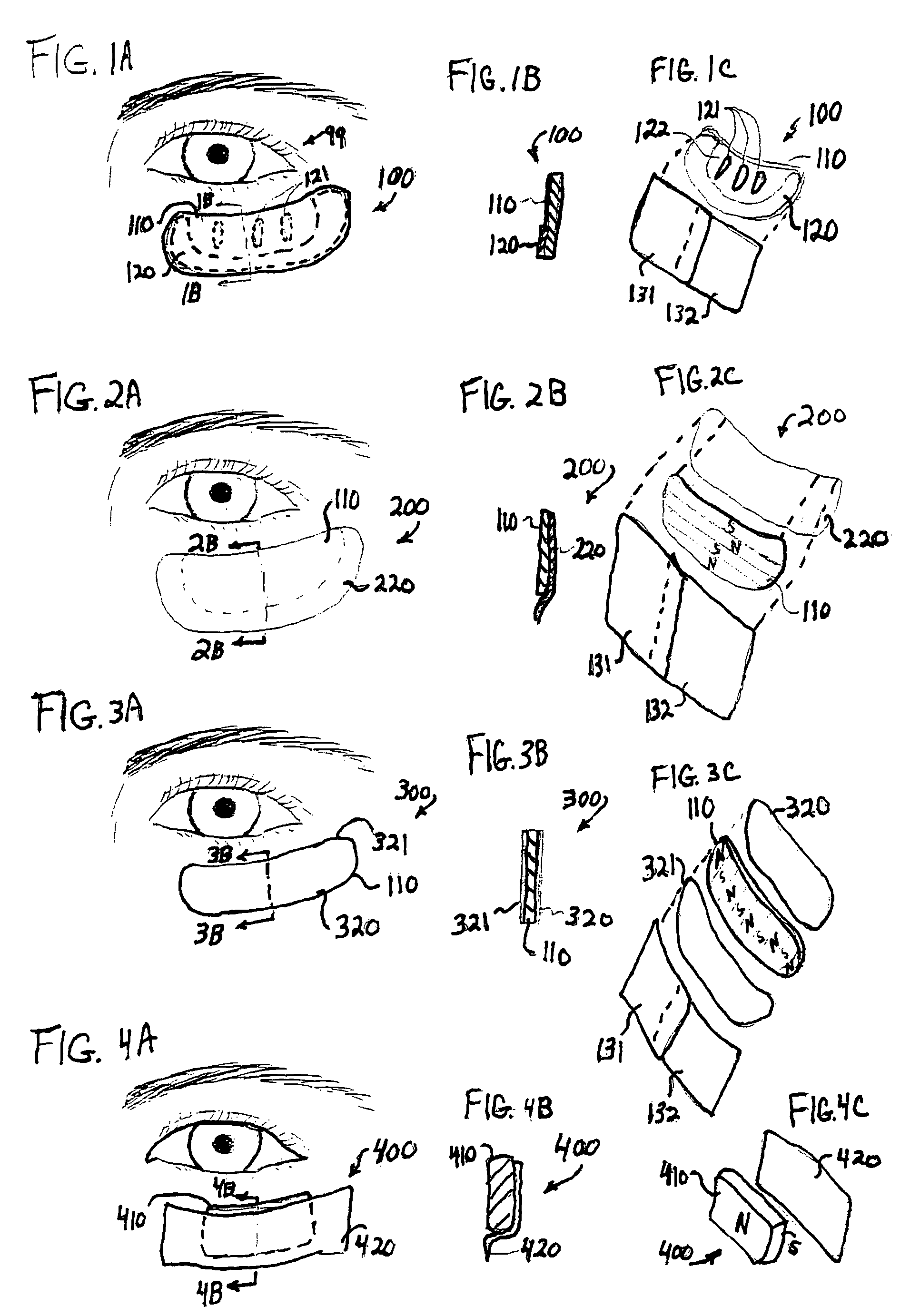
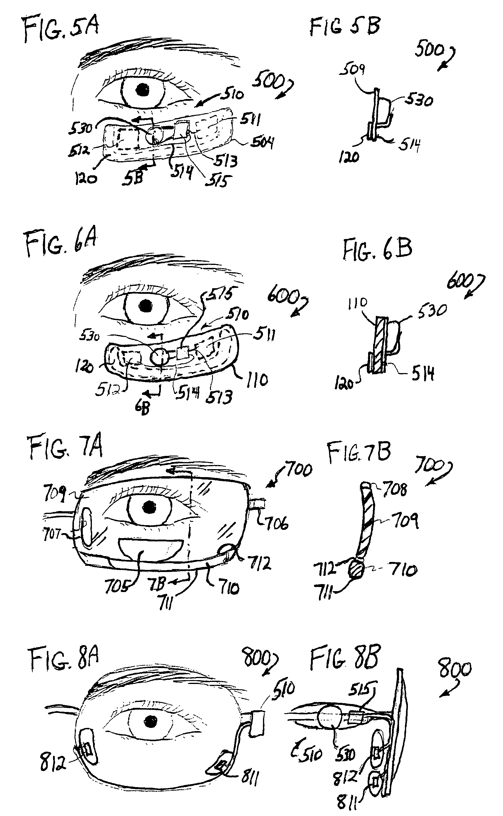
[0048]In the following detailed description of the preferred embodiments, reference is made to the accompanying drawings that form a part hereof, and in which are shown by way of illustration specific embodiments in which the invention may be practiced. It is understood that other embodiments may be utilized and structural changes may be made without departing from the scope of the present invention.

[0049]The leading digit(s) of reference numbers appearing in the Figures generally corresponds to the Figure number in which that component is first introduced, such that the same reference number is used throughout to refer to an identical component which appears in multiple Figures. Signals and connections may be referred to by the same reference number or label, and the actual meaning will be clear from its use in the context of the description.

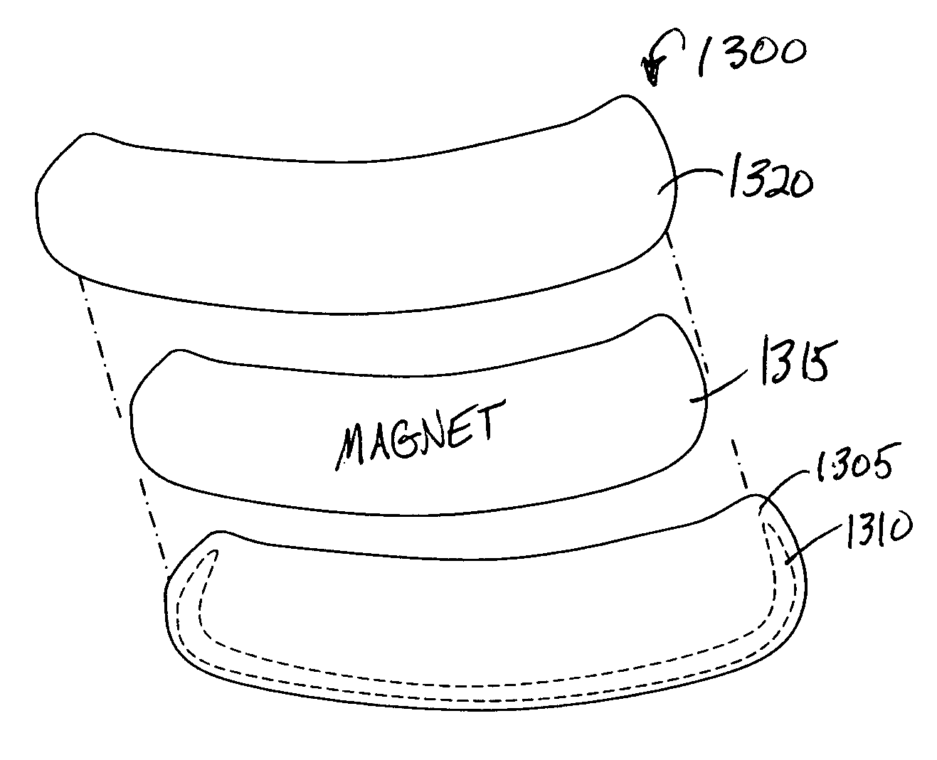
[0050]In some embodiments, the invention utilizes the rubberized magnetic material typically used to make “refrigerator magnets,” which typica...


PUM


Abstract

An apparatus and method for treating floater problems of the eye. In some embodiments, a magnet is non-invasively held in place against the face, and in particular, over the lower eyelid of the patient over an extended period of time, in order to control the position of the floaters and to stimulate the eye to better focus. In other embodiments, the device is included in eyeglasses that hold the magnet next to the lower eyelid. In some embodiments, the magnet is placed next to the lower eyelid. In some embodiments, the magnet is replaced by or supplemented with electrical stimulation. Some embodiments use a permanent magnet, while others use an AC or DC electromagnet. In some embodiments, a tapping device or heating device is included. The electro-magnetic force, tapping, and / or heat are controlled with a chip, circuit, and / or switch. In some embodiments, the device is placed under the skin.

Description

CROSS-REFERENCE TO RELATED INVENTION[0001]This invention claims benefit of U.S. Provisional Patent Application 60 / 614,882 filed Sep. 29, 2004, which is hereby incorporated by reference in its entirety.FIELD OF THE INVENTION[0002]This invention relates to methods and apparatus for reducing vision problems caused by floaters (a condition of the vitreous humor in the human eye), and more specifically to a non-invasive magnetic and / or electric remedy placed near the eye.BACKGROUND OF THE INVENTION[0003]Occasionally people will see small spots or “floaters” in their field of vision. Floaters are sometimes described as blurred spots or strands that can be seen floating through a normal field of vision, typically more pronounced against a bare wall or a blue sky. For most people, floaters do not severely impede vision. However, for some people, particularly after laser-surgery or other trauma, the problem becomes severe and prevents the ability of the eye to focus properly.[0004]Floaters a...

Claims


Application Information

Patent Timeline
Patent Type & Authority Patents(United States)
IPC IPC(8): A61N1/00
CPCA61N1/36046A61N2/02A61N2/06
Inventor RADEMACHER, PATRICK J.RADEMACHER, JOANN K.SMITH, JASON D.LEMAIRE, CHARLES A.
Owner RADEMACHER PATRICK J
Why Eureka
Try Eureka