Automatic residual fuel vent device for carburetor

a technology of residual fuel and vent device, which is applied in the direction of fuel injection apparatus, float-controlled apparatus, charge feed system, etc., can solve the problems of engine starting faults, poor running, and undesirable in the environment, so as to reduce the number of components, reduce the cost, and reduce the effect of malfunction

Inactive Publication Date: 2010-08-17
HONDA MOTOR CO LTD
View PDF36 Cites 17 Cited by
  • Summary
  • Abstract
  • Description
  • Claims
  • Application Information

AI Technical Summary

Benefits of technology

[0020]In accordance with the aspects of the present invention, residual fuel within the float chamber can reliably be returned to the fuel tank by negative pressure accumulated in the negative pressure surge tank, in particular even after the engine is stopped; furthermore, residual fuel can be vented by a single changeover cock, the number of components can be reduced thus enabling the device to be provided at a low cost, and there are fewer malfunctions and high reliability.

Problems solved by technology

Conventionally, in an engine equipped with a float type carburetor, such as a general purpose small engine, if the engine is left for a long period of time in an unused state with fuel remaining in a float chamber of the carburetor, the residual fuel gradually oxidizes and forms a gum within the float chamber, the fuel clogs a main jet or a breather hole, thus causing engine starting faults or poor running, and there is also the problem that when the engine is tilted the residual fuel flows into an intake passage through a nozzle.
In order to solve such problems, conventionally a drain plug is provided in a lower part of the carburetor, and after the engine is used or before it is stored the drain plug is manually operated so as to drain the residual fuel, but such an operation is not only troublesome and difficult but also undesirable in terms of the environment because of contamination of the surroundings of the engine, which is a problem.

Method used


Image

  • Automatic residual fuel vent device for carburetor
  • Automatic residual fuel vent device for carburetor
  • Automatic residual fuel vent device for carburetor

Examples


first embodiment

[0061]the present invention is now explained by reference to FIGS. 1 to 8.

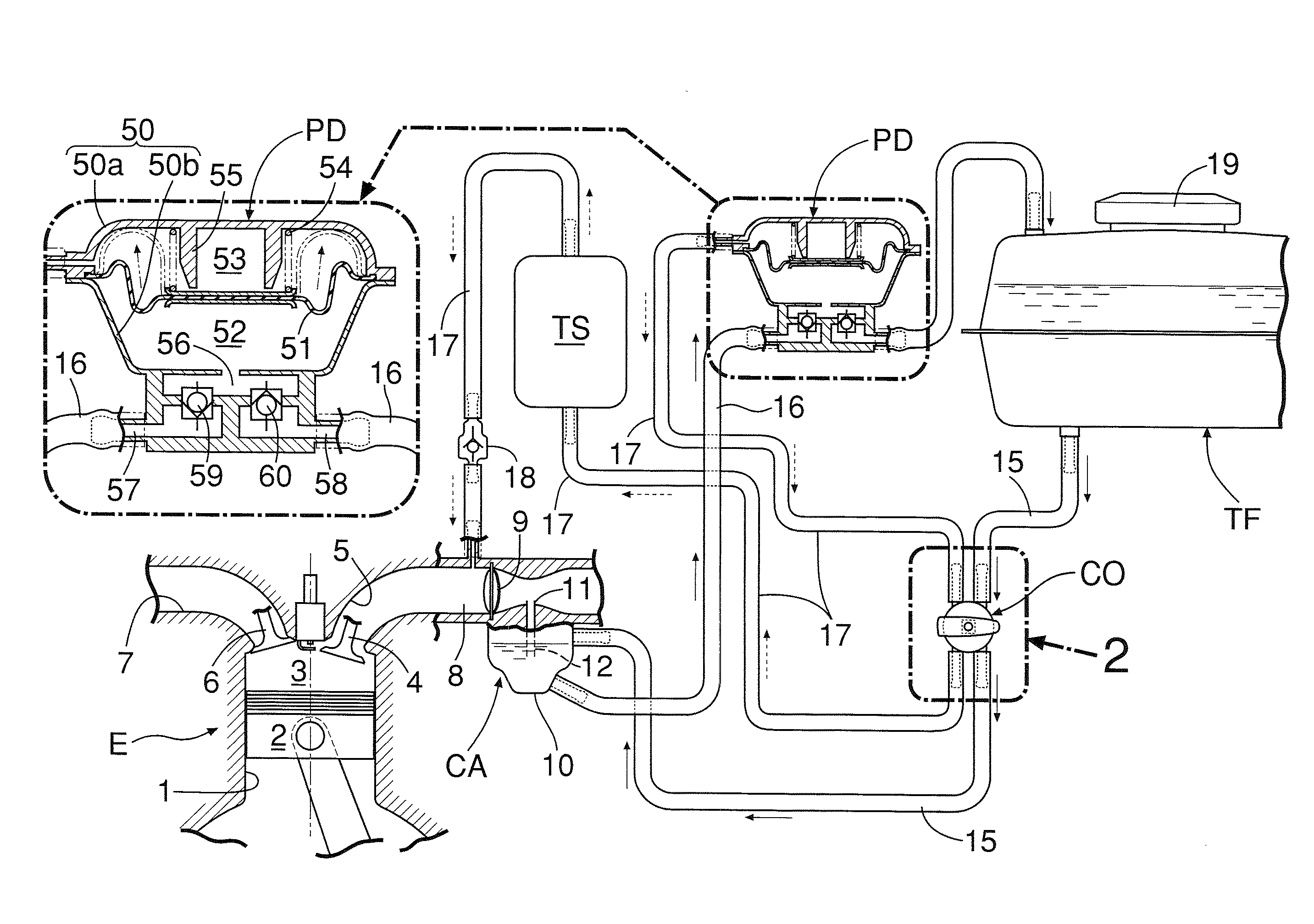
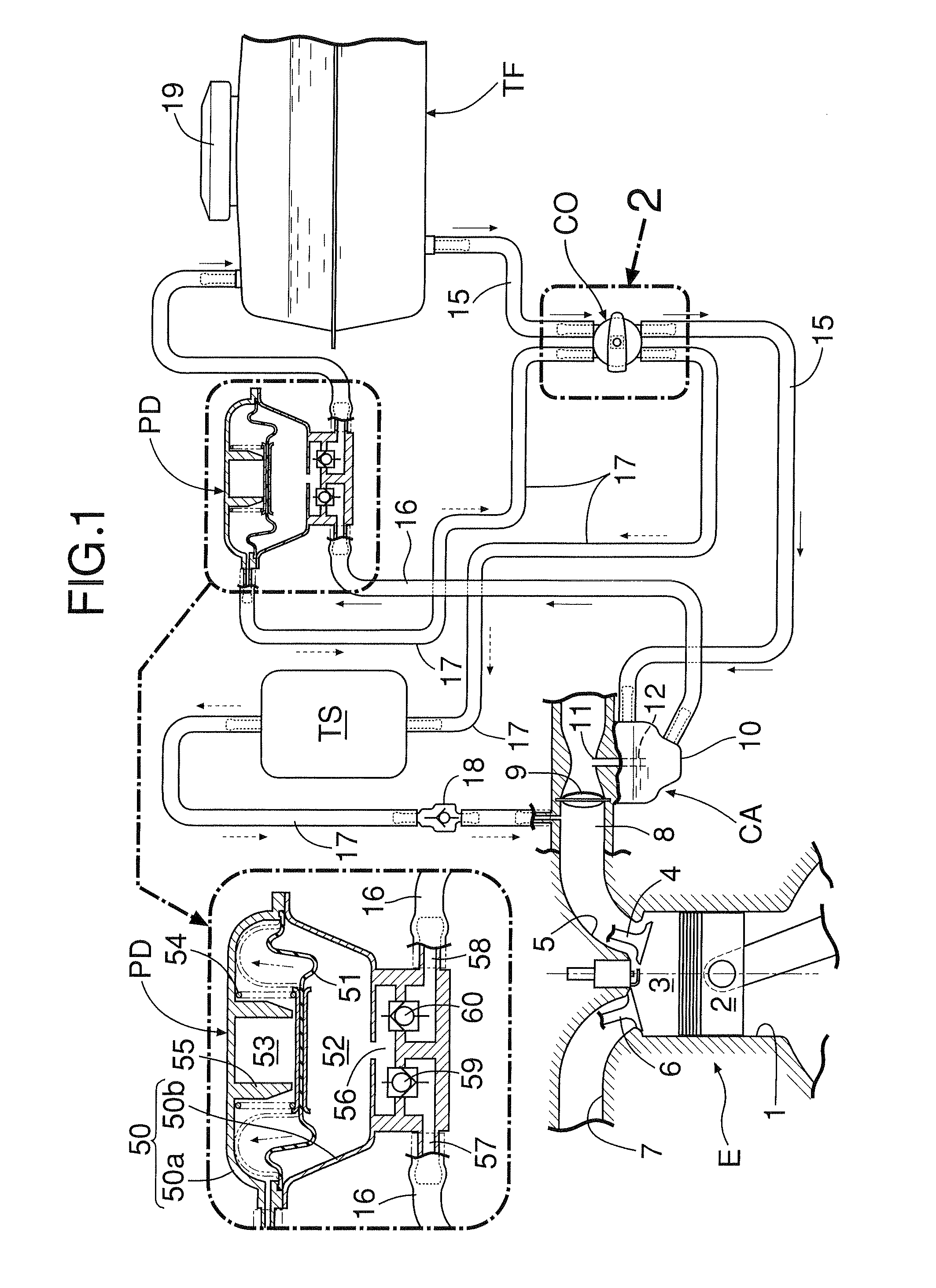
[0062]In FIG. 1, a general purpose engine E is an OHV type four cycle engine, in which a combustion chamber 3, at the top of a piston 2, of a cylinder 1 communicates with an intake port 5, which is opened and closed by an intake valve 4, and an exhaust port 7, which is opened and closed by an exhaust valve 6. Connected to an intake passage 8 communicating with the intake port 5 is a conventionally known float type carburetor CA, which controls the supply of a fuel-air gas mixture to the intake passage 8, and provided in the intake passage 8 on the downstream side of the carburetor CA is a throttle valve 9. The float type carburetor CA is equipped as usual with a float chamber 10 storing a fixed amount of fuel, the interior of the float chamber 10 communicates with a venturi part of the intake passage 8 via a main nozzle 11, and a main jet 12 immersed in fuel is provided at the lower end of the main nozzle 11.

[...

second embodiment

[0077]the present invention is now explained by reference to FIGS. 9 and 10.

[0078]This second embodiment has some differences from the first embodiment in terms of the arrangement of a changeover cock CO, but the arrangement is otherwise the same as the first embodiment; elements that are the same as those of the first embodiment are denoted by the same reference numerals and symbols.

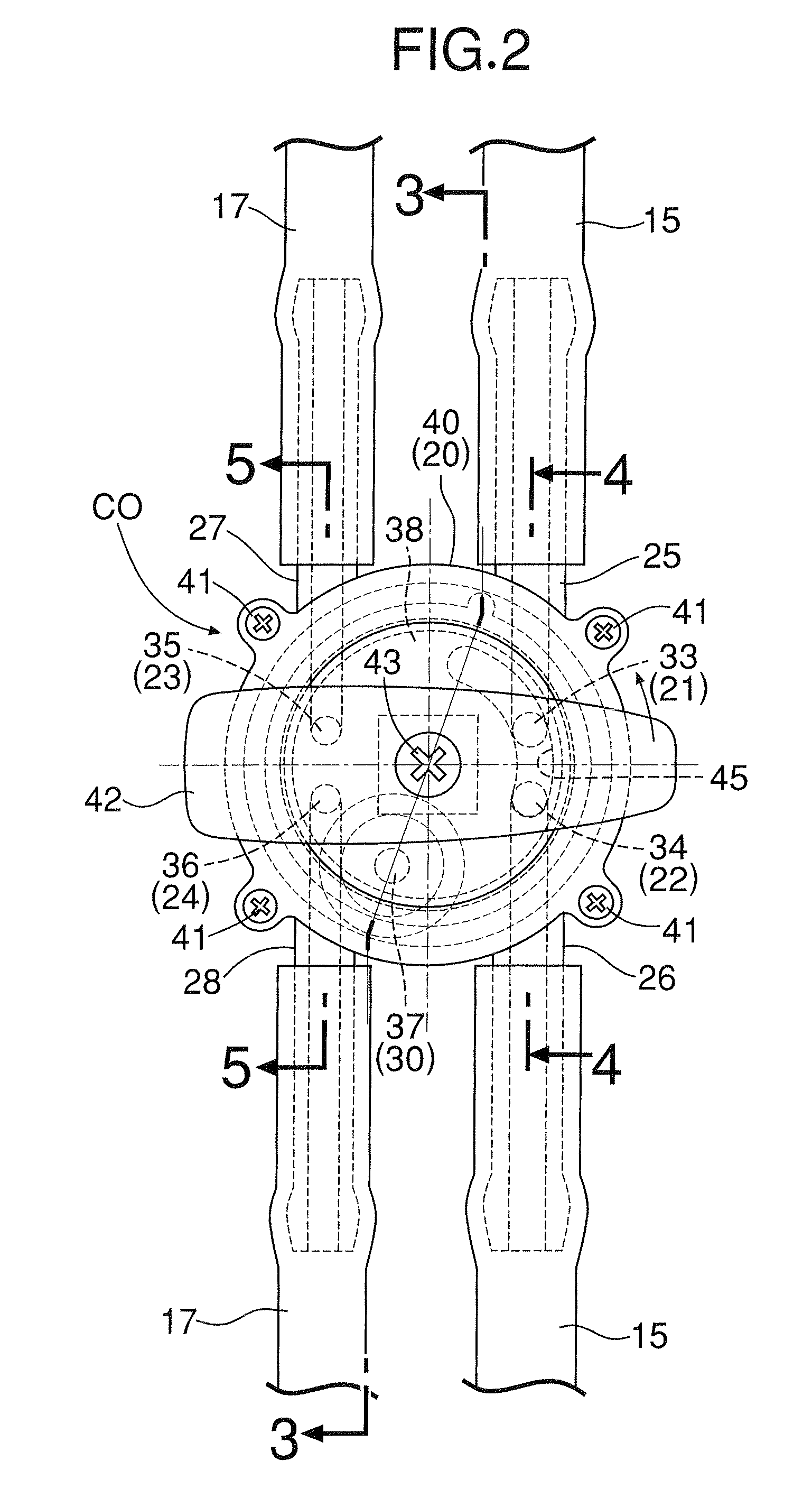
[0079]An arc-shaped first communication groove 145(1) and second communication groove 145(2) are bored in a disk-shaped cock body 38, which is rotatably housed within a cylindrical hollow cock case 20, so as to have the center of rotation of the cock body 38 as their centers and be spaced in the circumferential direction and in the radial direction. The circumferential length of the first communication groove 145(1) is shorter than that of the second communication groove 145(2).

[0080]In this second embodiment, residual fuel within a float chamber 10 can be vented while making the angle of rotation of th...

third embodiment

[0085]the present invention is now explained by reference to FIGS. 11 and 12.

[0086]This third embodiment has some differences from the first and second embodiments in terms of the arrangement of a changeover cock CO, but elements that are the same as those of the first and second embodiments are denoted by the same reference numerals and symbols.

[0087]One arc-shaped communication groove 245 is bored in a disk-shaped cock body 38 rotatably housed within a hollow cylindrical cock case 20 with the center of rotation of the cock body 38 as its center; the circumferential length of the communication groove 245 is shorter than that of the communication groove 45 of the first embodiment, and an atmosphere communication opening 30 provided in the cock body 38 on a concentric circle with first to fourth ports 21 to 24 is positioned in the vicinity of the third port 23. When venting fuel, the cock body 38 is rotated in a clockwise direction in FIGS. 11 and 12. In this third embodiment, by add...


PUM


Abstract

An automatic residual fuel vent device for a carburetor, the device including a fuel supply passage (15) connecting a fuel tank (TF) and a float chamber (10), a negative pressure passage (17) connecting an intake passage (8) and a negative pressure operating chamber (53) of a diaphragm pump (PD), a fuel vent passage (16) connecting the float chamber (10) and the fuel tank (TF), a single changeover cock (CO) provided so as to straddle the fuel supply passage (15) and the negative pressure passage (17), a negative pressure surge tank (TS) provided in the negative pressure passage (17), and the diaphragm pump (PD), which is connected to the fuel vent passage (16) and is operated by negative pressure of the negative pressure surge tank (TS), residual fuel of the float chamber (10) being returned to the fuel tank (TF) by the diaphragm pump (PD) operated by negative pressure from the negative pressure surge tank (TS) in accordance with the changing over of the changeover cock (CO). This enables residual fuel within the float chamber of the carburetor to be reliably returned to the fuel tank by intake negative pressure accumulated in the negative pressure surge tank and, furthermore, residual fuel can be vented by the changing over of a single changeover cock, thus enabling the number of components to be reduced and the device to be provided at a low cost.

Description

CROSS-REFERENCE TO RELATED APPLICATION[0001]This application is a National Stage entry of International Application No. PCT / JP2007 / 064955, filed Jul. 31, 2007, which claims priority to Japanese Application No. 2006-209824, filed Aug. 1, 2006, the disclosure of the prior applications are hereby incorporated in their entirety by reference.TECHNICAL FIELD[0002]The present invention relates to an automatic residual fuel vent device for a carburetor in an engine equipped with a float type carburetor, in which, when the engine is stopped, fuel remaining in a float chamber is returned to a fuel tank by utilizing negative pressure from a negative pressure generating part of the engine.BACKGROUND ART[0003]Conventionally, in an engine equipped with a float type carburetor, such as a general purpose small engine, if the engine is left for a long period of time in an unused state with fuel remaining in a float chamber of the carburetor, the residual fuel gradually oxidizes and forms a gum withi...

Claims


Application Information

Patent Timeline
Patent Type & Authority Patents(United States)
IPC IPC(8): F02M5/10F02D17/04
CPCF02M5/12F02M37/0023F02M37/0052F02M37/046
Inventor KONO, MASAKATSUIINO, KEIJIOOTA, YOSHITAKA
Owner HONDA MOTOR CO LTD
Why Eureka
Try Eureka