Ink jet recording head and recording apparatus

a recording head and recording apparatus technology, applied in printing and other directions, can solve the problems of increasing cost and size, affecting the reliability of the liquid discharge substrate, and the disadvantage of the adhesive or sealing agent flowing into the liquid discharge substrate ink supply port, etc., and achieve the effect of high reliability

Inactive Publication Date: 2010-08-17
CANON KK
View PDF17 Cites 45 Cited by
  • Summary
  • Abstract
  • Description
  • Claims
  • Application Information

AI Technical Summary

Benefits of technology

[0009]It is an object of the present invention to provide a highly reliable ink jet recording head capable of solving the above-stated disadvantages and to provide an ink jet recording apparatus that employs the recording head.
[0010]It is another object of the present invention to provide an ink jet recording head configured so that a side surface of the liquid supply port of an electrical wiring member is covered with a sealing agent, whereby it is possible to suppress ink that is a recording liquid from entering a wiring formed on the electrical wiring member and present on the side surface of the liquid supply port thereof and to suppress elution from being generated in the ink. In addition, it is another object of the present invention to provide an ink jet recording apparatus that employs the recording head.
[0011]It is yet another object of the present invention to provide an ink jet recording head that can seal an electrical connection portion by filling up a sealing agent between a liquid discharge substrate and an electrical wiring member, and that can prevent the sealing agent from flowing into a liquid supply port of the liquid discharge substrate when a liquid partition wall which prevents the liquid from leaking to surroundings of the liquid supply port. In addition, it is yet another object of the present invention to provide an ink jet recording apparatus that employs the recording head.

Problems solved by technology

This disadvantage is conspicuous particularly if an adhesive or a sealing agent is used in the liquid partition wall of each ink supply port.
As a result, if the position of the end surface of the ink supply port of the support substrate overlaps with that of the ink supply port of the liquid discharge substrate, the adhesive or sealing agent disadvantageously flows into the ink supply port of the liquid discharge substrate.
Besides, in the ink jet head, a desire to arrange a plurality of liquid discharge substrates as narrow as possible at high density from viewpoints of cost and size rises.
However, the support substrate disclosed in FIG. 18 has sufficiently large thickness, with the result it is difficult to form the narrow ink supply port with high accuracy.

Method used


Image

  • Ink jet recording head and recording apparatus
  • Ink jet recording head and recording apparatus
  • Ink jet recording head and recording apparatus

Examples


embodiments

[0031]Embodiments of the present invention will be described hereinafter with reference to the drawings.

first embodiment

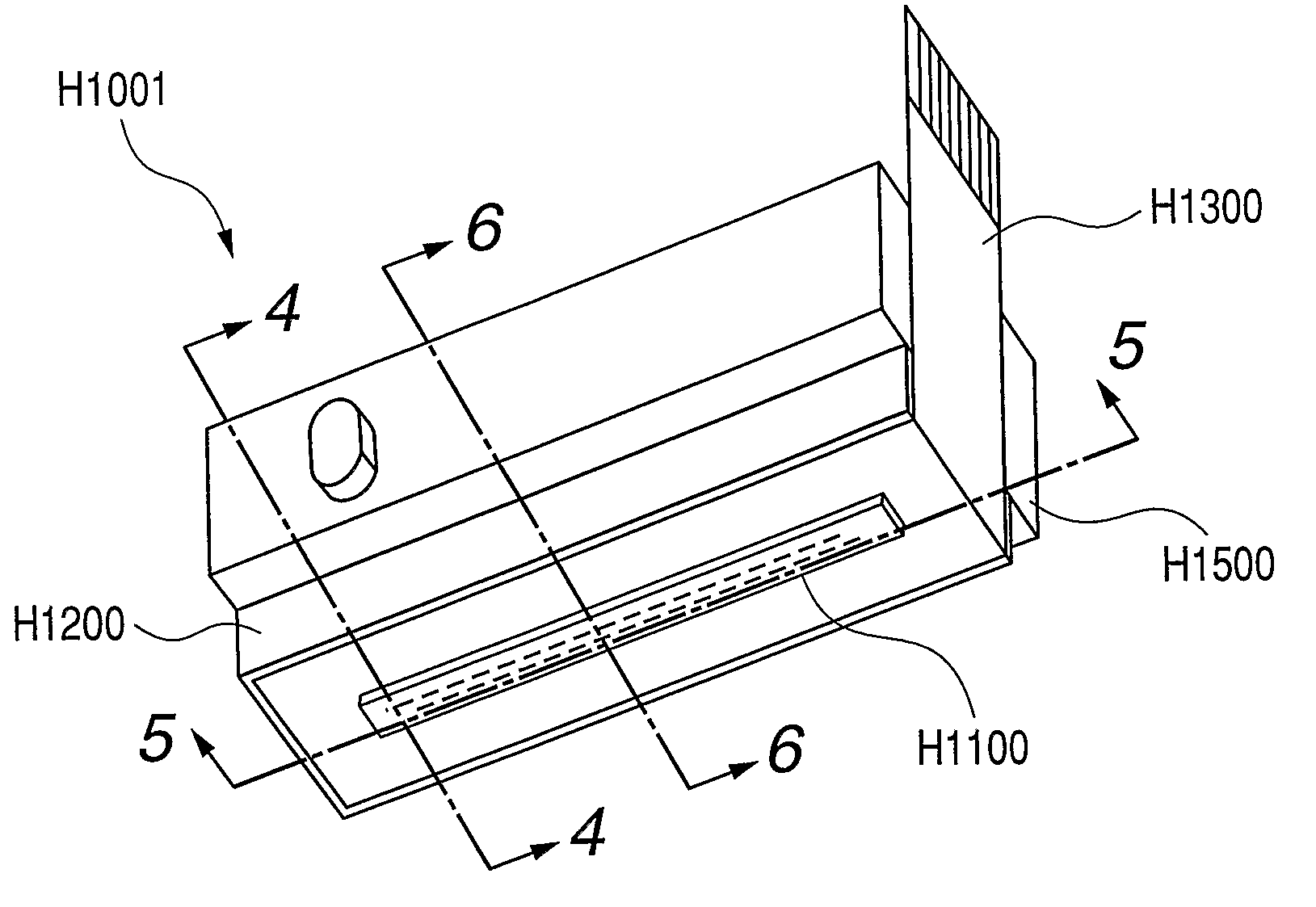
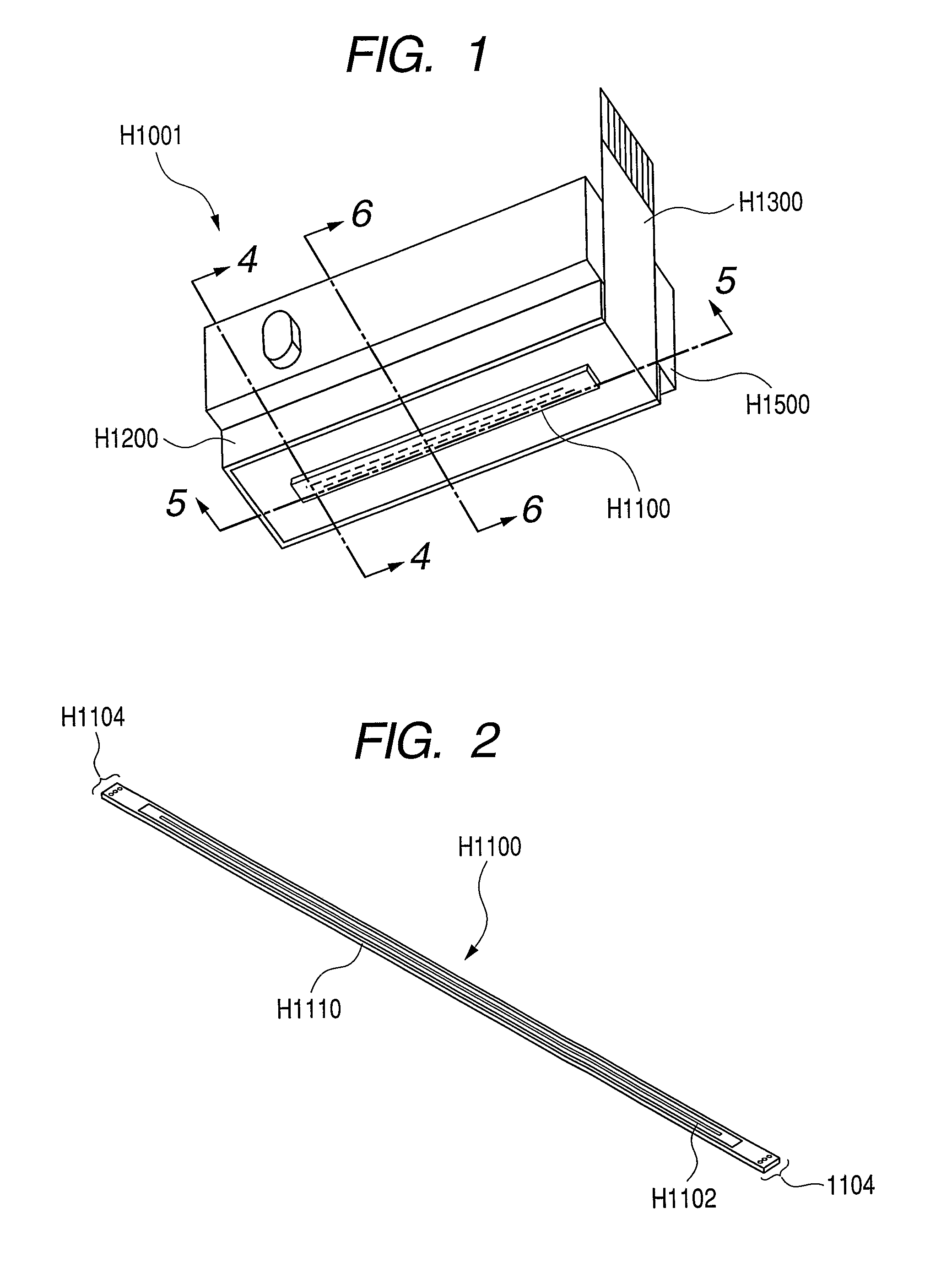
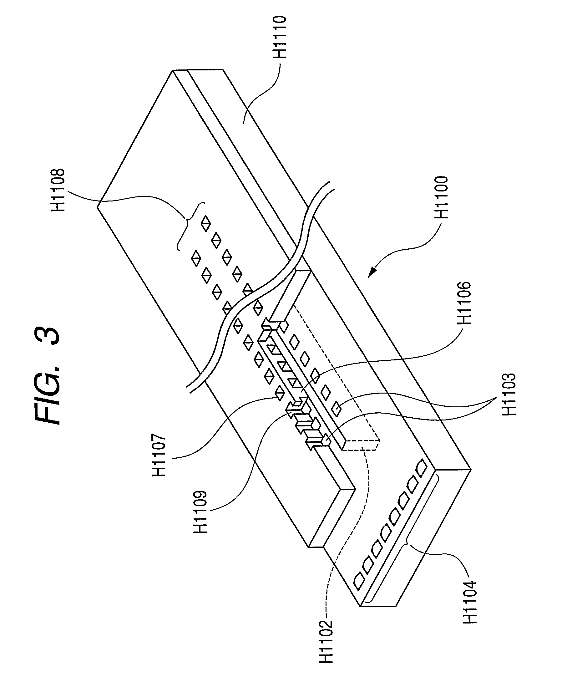
[0032]FIG. 1 is an external perspective view that shows an overall ink jet recording head according to a first embodiment of the present invention. FIG. 2 is a schematic perspective view of a liquid discharge substrate used in the ink jet recording head shown in FIG. 1. FIG. 3 is a partial, enlarged perspective view of the ink jet recording head shown in FIG. 2.

[0033]FIG. 4 is a typical view that shows a section taken along 4-4 of FIG. 1 and that is a sectional view near an electrode. FIG. 5 is a typical view that shows a section taken along 5-5 of FIG. 1. FIG. 6 is a typical view that shows a section taken along 6-6 of FIG. 1.

[0034]A recording head H1001 shown in FIG. 1 is fixedly supported by positioning means of a carriage (not shown) mounted on an ink jet recording apparatus main body and an electrical contact. An ink tank (not shown) is detachable to the recording head H1001. Since the ink tank is replaceable, running cost for recording by an ink jet recording apparatus is redu...

second embodiment

[0052]A second embodiment of the present invention will be described. In this embodiment, differences of the second embodiment from the first embodiment will be mainly described.

[0053]FIGS. 8A and 8B show the second embodiment of the present invention. FIG. 8A is a typical view that shows a section taken along 5-5 of FIG. 1 and FIG. 8B is a typical view that shows a section taken along 6-6 of FIG. 1.

[0054]In this embodiment, the liquid supply port H1301 of the flexible wiring substrate H1300 is formed to be larger than the liquid supply port H1102 of the liquid discharge substrate H1100 and to be substantially equal in size to the liquid supply port 1201 of the holding member H1200.

[0055]The side surface of the liquid supply port H1301 of the flexible wiring substrate H1300 is completely sealed by the adhesive or sealing agent.

[0056]For instance, the adhesive or sealing agent filled up between the liquid discharge substrate H1100 and the flexible wiring substrate H1300 is sufficient...


PUM


Abstract

A highly reliable, small-sized, and inexpensive ink jet recording head includes an electrical wiring member that is joined with a back surface of a liquid discharge substrate and includes a liquid supply port communicating with a liquid supply port of the liquid discharge substrate and an electrical connection portion connected to the electrode; and a holding member that holds the liquid discharge substrate through the electrical wiring member and includes a liquid supply port for supplying the liquid to the liquid supply port of the liquid discharge substrate. The liquid supply ports of the electrical wiring member, the liquid discharge substrate, and the holding member communicate with one another. A sealing agent for sealing the electrical connection portion is filled up between the liquid discharge substrate and the electrical wiring member, and a side surface of the liquid supply port of the electrical wiring member is covered with the sealing agent.

Description

TECHNICAL FILED[0001]The present invention relates to a recording head adapted to a recording device that discharges a recording liquid such as ink and that performs a recording operation. More specifically, the present invention relates to connection between a liquid discharge substrate adapted to this recording head and a wiring member.BACKGROUND ART[0002]Generally, an ink jet recording head employed in an ink jet recording apparatus includes an ink jet recording head for forming a droplet of ink or the like and a supply system that supplies the ink or the like to this recording head.[0003]As for connection between a liquid discharge substrate adapted to this recording head and a wiring member, a wide array ink jet device configured by a print head substrate having electric connection electrodes formed on an opposite surface to a surface on which a discharge port is formed is disclosed in Japanese Patent Application Laid-Open No. 11-192705. FIGS. 17 and 18 show a wide array ink je...

Claims


Application Information

Patent Timeline
Patent Type & Authority Patents(United States)
IPC IPC(8): B41J2/05B41J2/14
CPCB41J2/14072B41J2/155B41J2/1603B41J2/1623
Inventor HIROSAWA, TOSHIAKIIWANAGA, SHUZOWATANABE, YASUTOMOSAITO, RIICHI
Owner CANON KK
Why Eureka
Try Eureka