Bus bar connection for a gas-insulated switchboard system

Inactive Publication Date: 2010-08-17
AREVA T&D
View PDF12 Cites 5 Cited by
  • Summary
  • Abstract
  • Description
  • Claims
  • Application Information

AI Technical Summary

Benefits of technology

[0009]It is particularly advantageous if the bellows be arranged so as to be axially displaceable. If this is done, it is very simple to dismantle the switchboard system since an air gap can be left between the switchboard sections because of the flexible bellows.
[0010]It is also particularly advantageous if the bellows are of metal, and if the bellows incorporate seals as well as attachment elements that can be installed from outside the bellows and which produce a positive and force-derived seal with the outside walls of the switchboard sections. In this connection, it is advantageous if the sealing elements include annular seals and if the attachment elements include screw-type connectors.
[0011]Because of these additional measures, it is made particularly simple to install the bellows from the outside and provision is made for easy-to-install, flexible sealing against gas leaks.
[0012]A particular advantage is also gained if the electrical connection element of the bus bar connection makes an electrically conductive clamped connection between the switchboard sections. In this connection, it is an advantage if th

Problems solved by technology

In addition, gas sealing in the area of the connection also imposes significa

Method used


Image

  • Bus bar connection for a gas-insulated switchboard system
  • Bus bar connection for a gas-insulated switchboard system
  • Bus bar connection for a gas-insulated switchboard system

Examples


Embodiment Construction

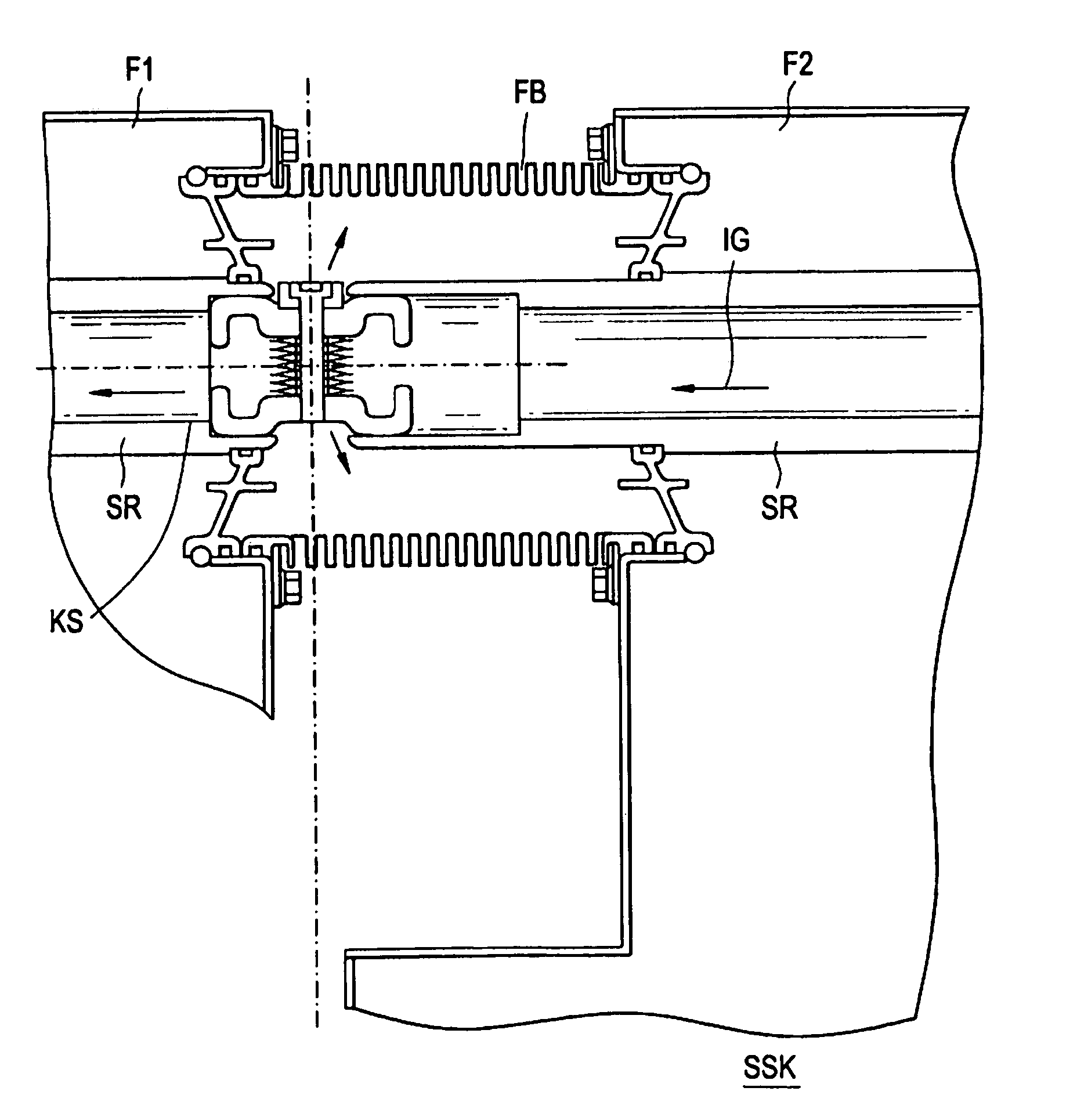
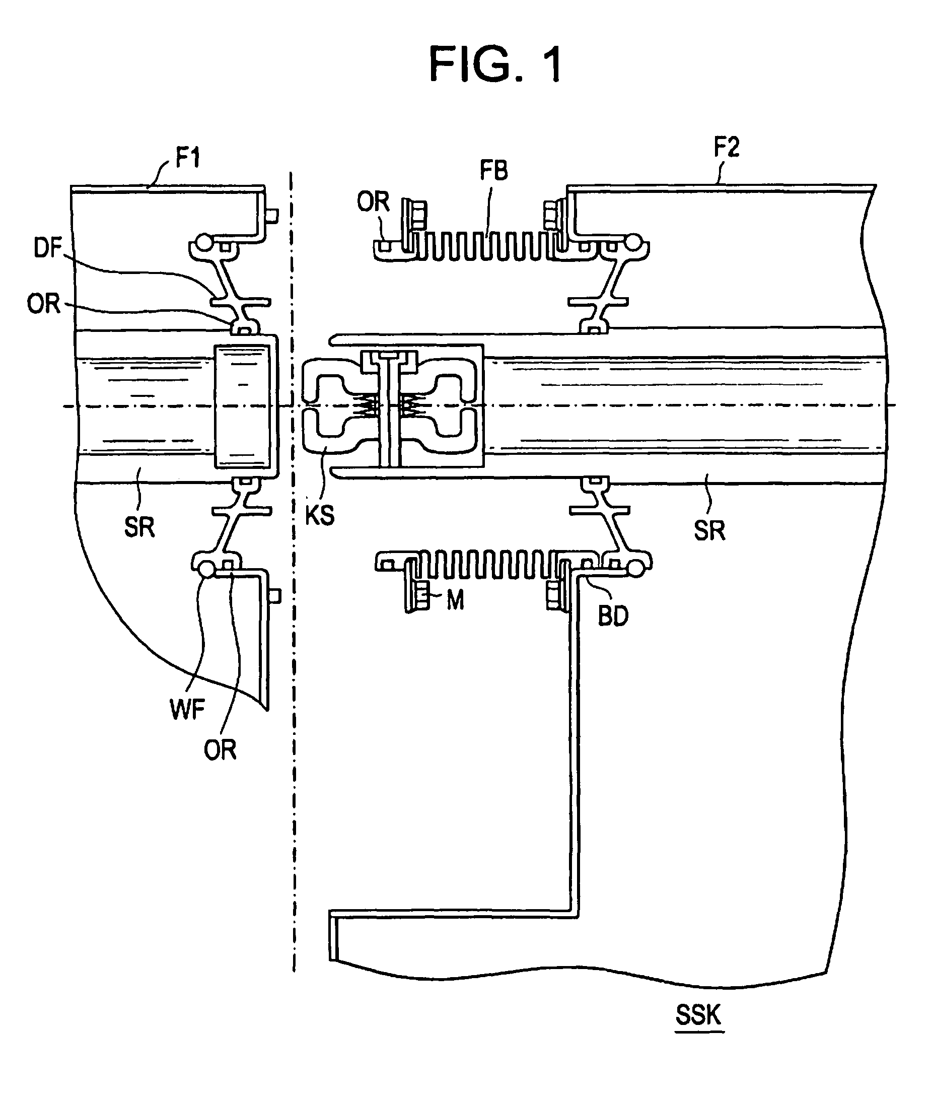
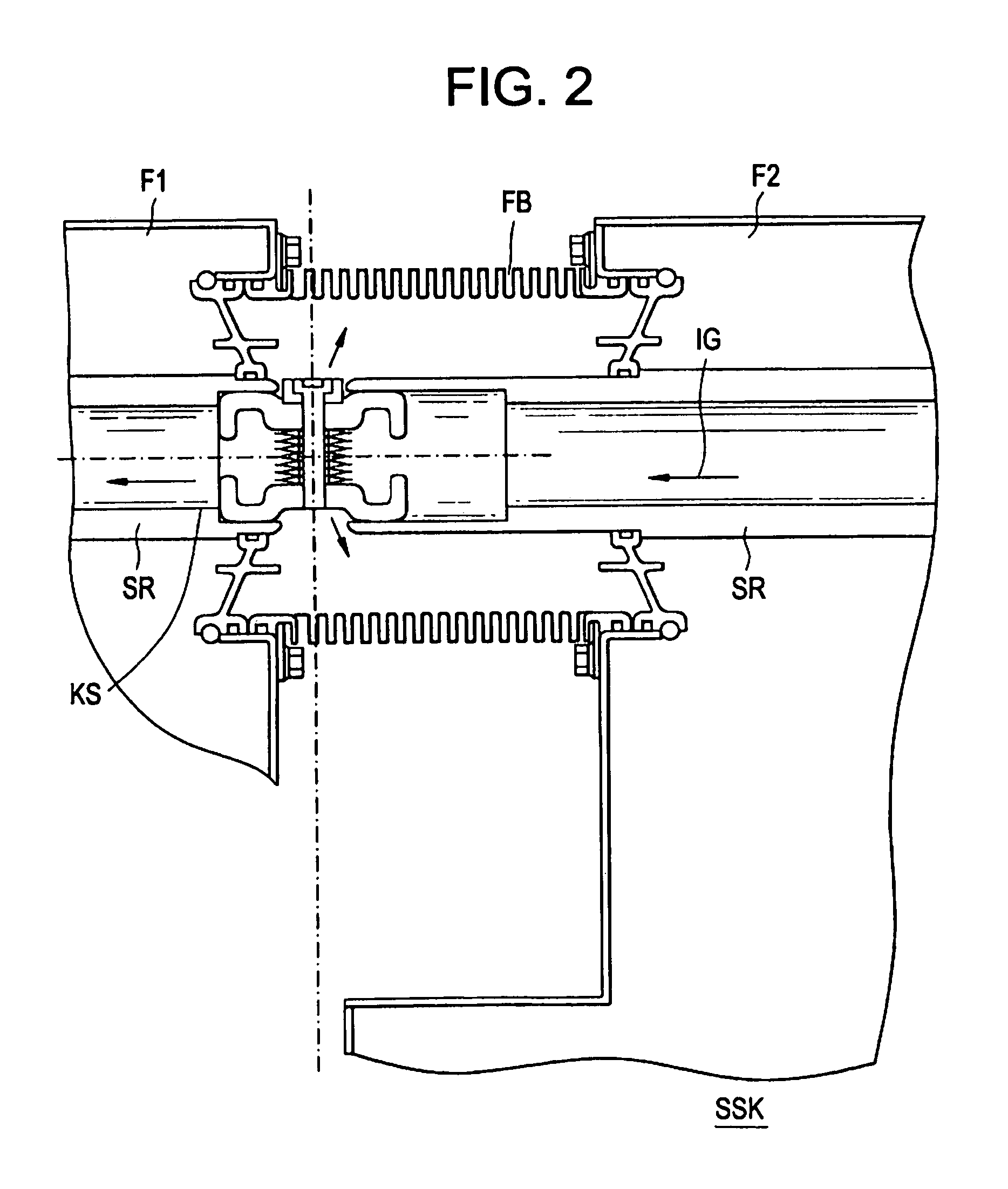
[0018]FIG. 1 shows a cross section through a bus bar connection SSK when disconnected; this is intended to connect two switchboard sections F1 and F2 (left-hand and right-hand sections of the drawing) that are to be connected to one another.

[0019]Within the gas containers of the two switchboard sections F1 and F2 there are bus bar tubes SR1, SR2, one end of each of these extending from the container so as to be gastight, in order that they can be connected to one another through the bus bar connection SSK. The gas chambers GR1 and GR2 of the switchboard sections F1, F2 are filled with protective and insulating gas at the factory.

[0020]The bus bar tubes SR1 and SR2 are coaxial with one another and the ends of each extend through a channel DF that is sealed off with sealing rings OR, in this instance O-ring seals. All the channels DF are located on a container support BD and are sealed with O-rings OR to prevent the egress of insulating gas. The bus bar tube SR2 of the second switchbo...


PUM


Abstract

A bus bar connection which electrically interconnects switchboard sections by at least one electrical connection element, the bus bar connection including bellows which can be mounted between the switchboard sections, can be filled with insulting gas, and surround the electrical coupling element of the bus bar connection in a gas-tight manner.

Description

PRIORITY STATEMENT[0001]This application is the national phase under 35 U.S.C. §371 of PCT International Application No. PCT / EP2003 / 009080 which has an International filing date of Aug. 16, 2003, which designates the United States of America, and which claims priority on German patent application number 10246598.3 filed Oct. 5, 2002, the entire contents of each of which are hereby incorporated herein by reference.FIELD[0002]The present invention relates to a bus bar connection, and to a gas-insulated switchboard system, in particular a gas-insulated medium-voltage system, which is fitted with the bus bar connection.DESCRIPTION OF THE RELATED ART[0003]In switchboard systems with gas-insulated switchboard sections or similar modules that are connected to one another through bus bar connections, exacting demands are imposed not only on the electrical contacts, but also on the gas seals themselves.[0004]Usually, for example, couplings with double-cone plug-type connectors are used and t...

Claims


Application Information

Patent Timeline
IPC IPC(8): H01R4/60H02B13/00H02B13/045
CPCH02B13/005H02B13/045H02G5/002
Inventor LISTL, PETERSTARCK, THIERRY
Owner AREVA T&D
Why Eureka
Try Eureka