
Method and instrumentation for vertebral interbody fusion

a technology of vertebral interbody and instrumentation, applied in the field of surgical procedures for spinal stabilization, can solve the problems of limiting the total number of complete distractor instruments required, tissue and vessel present in the working channel may be damaged, etc., to prevent tissue and vessel infiltration, reduce width, and limit the amount of retraction of surrounding vascular

Inactive Publication Date: 2010-08-17
WARSAW ORTHOPEDIC INC
View PDF50 Cites 46 Cited by
  • Summary
  • Abstract
  • Description
  • Claims
  • Application Information

AI Technical Summary

Benefits of technology

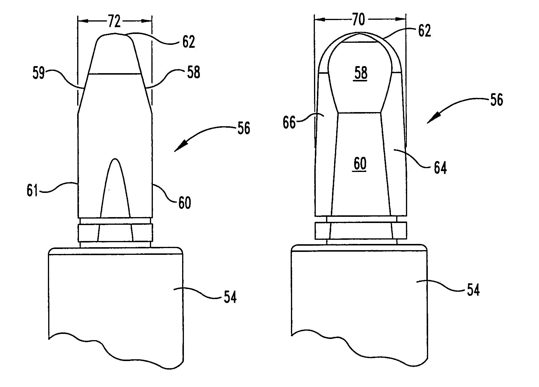
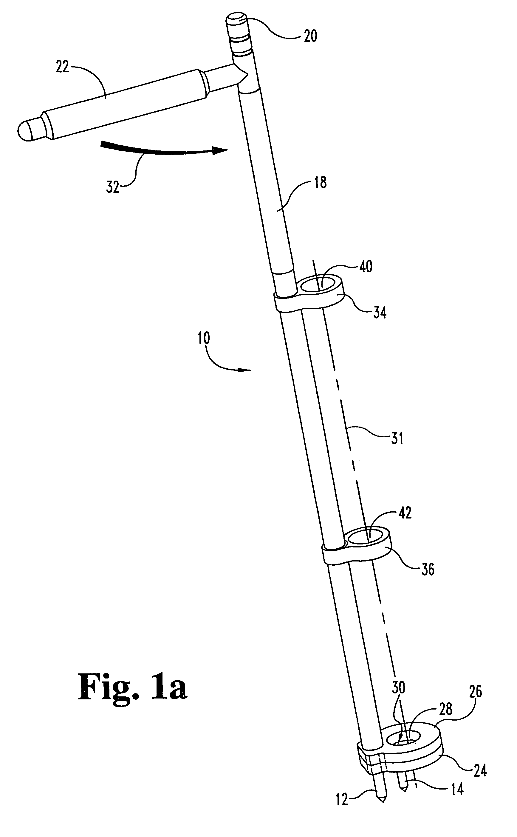
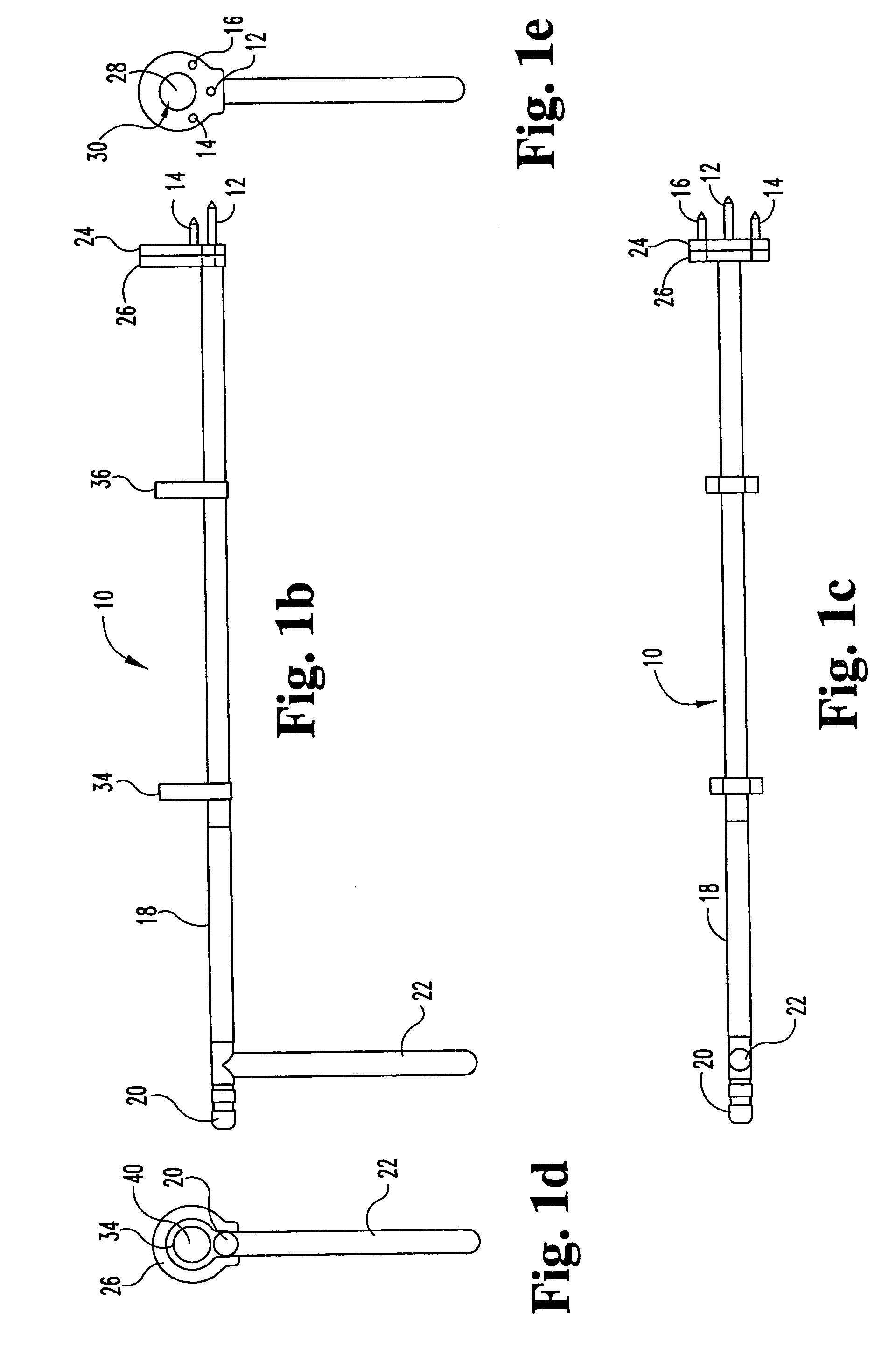
The present invention relates to methods and instrumentation for vertebral interbody fusion. The invention provides methods for accessing the spine, creating an opening in the disc space, and positioning an outer sleeve in the disc space. The invention also provides improved guide members for maintaining alignment of cutting instruments. The invention further includes a removable distal tip for the outer sleeve that can be left in the disc space, as well as a cover for the visualization window to prevent tissue and vessel infiltration. The invention also provides a double barrel sleeve configuration and a visualization window that can be opened and closed to prevent tissue and vessel infiltration. The invention also includes a manual adjustable depth stop for controlling the steps of trephining, reaming, tapping, and dowel insertion. The invention also includes an outer sleeve with a visualization window and a cover for the window.

Problems solved by technology

With such a configuration, a single distractor tool shaft may be use with various tips, thereby limiting the total number of complete distractor instruments required.
Tissue and vessels present in the working channel may be damaged by insertion and removal of the tools (often with cutting edges) or during use of those tools.

Method used


Image

  • Method and instrumentation for vertebral interbody fusion
  • Method and instrumentation for vertebral interbody fusion
  • Method and instrumentation for vertebral interbody fusion

Examples


Embodiment Construction

[0065]For the purposes of promoting an understanding of the principles of the invention, reference will now be made to the embodiments illustrated in the drawings and specific language will be used to describe the same. It will nevertheless be understood that no limitation of the scope of the invention is thereby intended, such alterations and further modifications in the illustrated device, and such further applications of the principles of the invention as illustrated therein being contemplated as would normally occur to one skilled in the art to which the invention relates.

[0066]The present invention relates to methods and instrumentation for performing vertebral interbody fusion. Specifically, although aspects of the present invention may have other uses either alone or in combinations, the instruments and methods disclosed herein are particularly useful for anterior lumbar interbody fusion. Provisional application No. 60 / 081,206 filed Apr. 9, 1998 is incorporated herein by refe...


PUM


Abstract

A method and instrumentation particularly adapted for disc space preparation from an anterior approach to the spine. In one aspect, an expandable template is provided having guides to guide a cutting device for bilateral formation of openings in the disc space. In another aspect, an improved guide member is provided for guiding a cutting tool. Still further, the invention provides an improved double barrel guide sleeve with a central distraction extension and lateral non-distracting extensions. Optionally, the guide sleeve includes windows and covers to selectively cover the windows. An improved reamer with an internal chamber and optional modular coupling is also provided. A depth stop is provided to selectively engage a tool shaft and a guide sleeve to control tool penetration into the disc space. A method of using the disclosed instruments is also provided.

Description

CROSS-REFERENCE TO RELATED APPLICATIONS[0001]This application is a divisional of U.S. patent application Ser. No. 10 / 166,306, filed Jun. 10, 2002 now U.S. Pat. No. 7,189,242, which is a divisional of U.S. patent application Ser. No. 09 / 287,917, filed Apr. 7, 1999, now U.S. Pat. No. 6,428,541 issued Aug. 6, 2002, which claims the benefit of U.S. Provisional Application No. 60 / 081,206, filed Apr. 9, 1998, all of which are incorporated by reference in their entirety.BACKGROUND OF THE INVENTION[0002]The present invention relates generally to surgical procedures for spinal stabilization and more specifically to instrumentation adapted for inserting a spinal implant within the intervertebral disc space between adjacent vertebra. More particularly, while aspects of the invention may have other applications, the present invention is especially suited for disc space preparation and implant insertion into a disc space from a generally anterior approach to the spine.[0003]Various surgical meth...

Claims


Application Information

Patent Timeline
Patent Type & Authority Patents(United States)
IPC IPC(8): A61B17/56A61B17/60A61B17/66A61F5/04
CPCA61B17/1757A61B2017/0256A61B2019/462A61B2090/062
Inventor BOYD, LAWRENCE M.RAY, III, EDDIEESTES, BRADLEY T.LIU, MINGYAN
Owner WARSAW ORTHOPEDIC INC
Learn More