
Method of processing topographic data in real time in an aircraft, in order to display said data

a topographic data and aircraft technology, applied in the field of real-time topographic data processing in the aircraft, can solve the problems of time-consuming and laborious, difficult to superimpose on the map background image other graphic information, and inability to follow in real-time the path of the aircraft, etc., and achieve the effect of less information

Inactive Publication Date: 2010-08-17
THALES SA
View PDF15 Cites 8 Cited by
  • Summary
  • Abstract
  • Description
  • Claims
  • Application Information

AI Technical Summary

Benefits of technology

[0021]The individual zones can be geo-referenced, by using the aircraft positioning and orientation data which is obtained by consolidating all the information sources available onboard the aircraft. For example, there is supplied, for each calculated radial, its angular orientation relative to geographic north. In another embodiment, it is possible to geo-reference the very geometrical form of the individual zones. In practice, they have a simple geometry, of polygon type, roughly triangular or trapezoid, which can be described by geo-referenced coordinates of their peaks: three points for a triangular angular segment section or four points for a trapezoid section. For each of these points, it is possible for example to transmit, in the display data frames, their altitude and their longitude. In this way, a suitable graphic display system can manipulate these simple, triangular or trapezoid geometrical shapes georeferenced by the peaks. It is also possible to describe the angular segment sections by the three peaks of the triangle including the radial and the distances between which the topographic data is calculated. Innovative display systems are in practice emerging which are capable of directly plotting such polygons to approach the forms of the initial radials. These systems can transform the graphic data to be presented into textures which can be likened to small images with false colours, which can be flattened and stretched on the defined polygons, using a graphics generation processor. By these means, the graphic artifacts are advantageously eliminated.
[0022]A method according to the invention makes it possible to refresh the displayed image only by individual zones, according to their update frequency, while remaining synchronous with the rest of the image: there is no point in each time supplying all the points of the operating zone to be mapped: there is less information to be processed and to be displayed. Furthermore, since the transmitted individual zones are fixed in a single terrestrial reference base (geo-reference of the origin and heading of the aircraft), and the display device used to represent them is fixed in an aircraft fix, said aircraft fix being mobile relative to the fixed terrestrial fix, then the movement of the aircraft induces a movement and a rotation of the map screen background in real time with the movement of the aircraft, such that the display effect or fixedness of the screen background observed in the systems of the state of the art is eliminated. It furthermore makes it possible to display in real time, in a geographically coherent manner on one and the same navigation screen, other geo-referenced graphic information such as the flight plan.
[0023]The definition of the individual zones, their update frequency and their priority are advantageously variable, according to the operational situation of the aircraft. In particular, if the speed of movement of the aircraft increases or reduces, the update frequency can be adapted; if the aircraft turns, the angle associated with an element can be widened within the turn to increase the number of radials within this turn; furthermore, it is possible to calculate a geometrically larger element so as to gather information in advance concerning the predicted movement of the aircraft, which makes it possible to have in advance geographic data relating to the future overflight zone of a given geographic element. This is very useful in the case where the airplane increases its speed or begins a turn.

Problems solved by technology

This graphic display mode based on radials does, however, have some drawbacks, including:the time to update a complete image, corresponding to a 360° sweep of the operating zone of the aircraft, is slow; if the position of the aircraft is superimposed on the map background, the latter is offset relative to the position of the aircraft, an offset which is marked if the aircraft is accelerating or turning.the display graphic data is not geographically referenced (or geo-referenced), for example with a latitude / longitude and an orientation relative to geographic north, because of the very nature of the radar-type sweep.
It is thus difficult to superimpose on the map background image other graphic information, such as the flight plan.
For these reasons, it is not possible to follow in real time the path of the aircraft: it is not possible to have the radials rotated or shifted with the aircraft.
There is therefore a display inconsistency with a delay effect.
This effect can be mitigated by increasing the update frequency, but this incurs a cost overhead in time and computation resources.the minimum resolution of the system that supplies the map data to be displayed is defined relative to the maximum range of the radials, which, for a given range, and a given application system, defines the angular aperture of the radials and the size of the points on each radial.

Method used


Image

  • Method of processing topographic data in real time in an aircraft, in order to display said data
  • Method of processing topographic data in real time in an aircraft, in order to display said data
  • Method of processing topographic data in real time in an aircraft, in order to display said data

Examples


Embodiment Construction

[0040]The figures show subdivisions and any numerical indications are only examples, given by way of indication. The invention is not limited to just these examples.

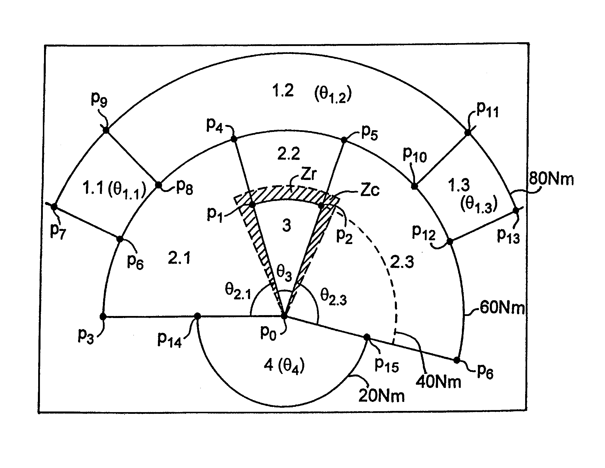
[0041]FIG. 3a gives a first example of a subdivision of an operating zone of an aircraft A into individual zones according to the operational interest of these individual zones, according to a method according to the invention.

[0042]The operational interest of an individual zone depends on different factors, including: the movement of the aircraft in a straight line (speed of movement) or in a turn (angular rotation speed), the situation in relation to the aircraft, front, back or side, the distance in relation to the aircraft.

[0043]These various aspects are taken into consideration together in combination, to determine an appropriate subdivision, according to different criteria. Among these criteria, the following criteria can be mentioned, in relation to FIG. 8a: [0044]The bearing angle φ of a radial R with the current...


PUM


Abstract

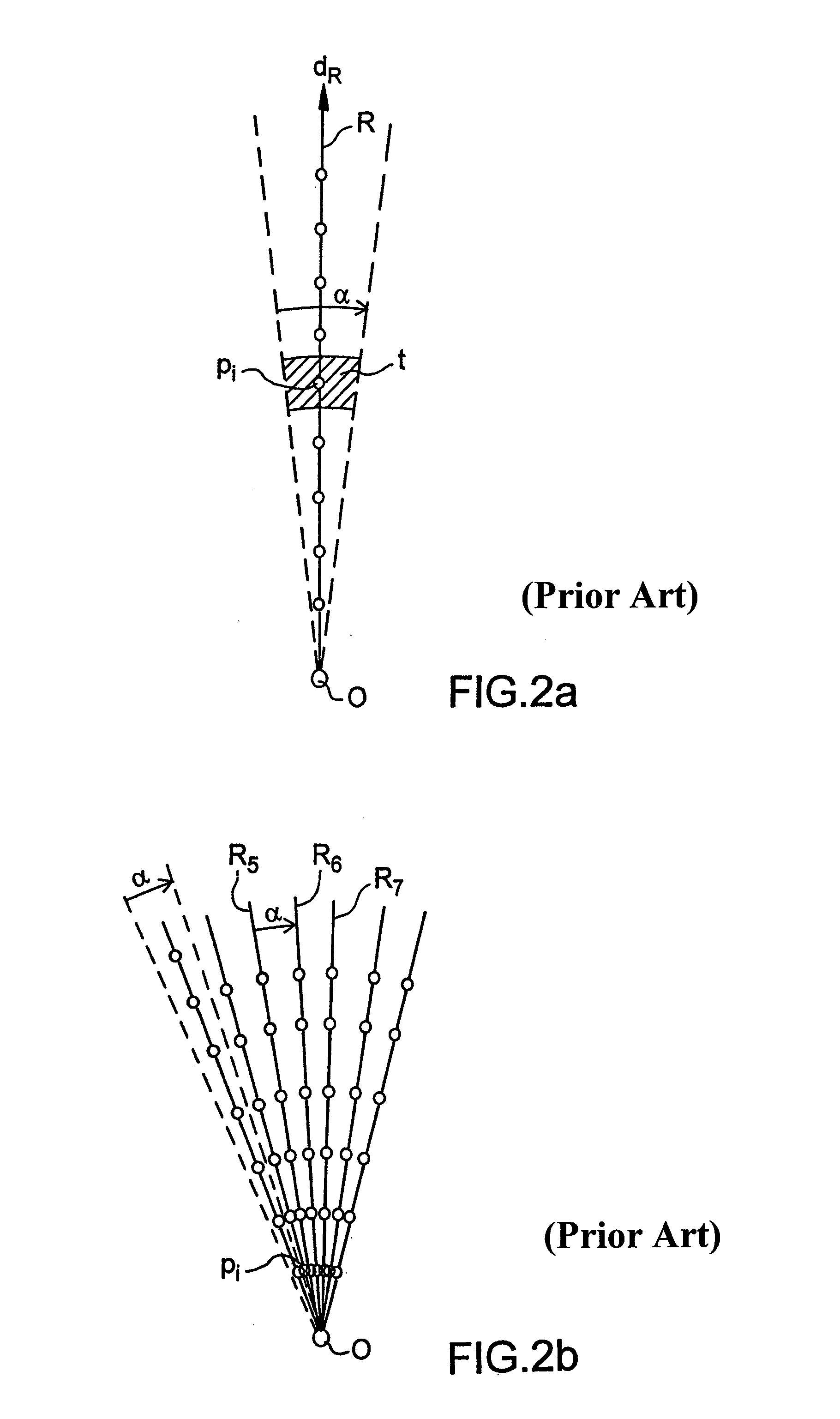
The field of the invention is that of the display in map form of an operating zone of an aircraft on a screen, and more particularly a method of processing topographic data of this operating zone of an aircraft in real time, based on a calculation of radials (R) centred on a reference point (O) defining an angular segment of topographic data. According to the invention, the method includes a subdivision of the operating zone to be mapped into a plurality of angular segment sections, each forming an individual zone (3), and an assignment of a processing priority and a refresh frequency specific to each individual zone defined according to a criterion of operational interest of the element to the aircraft.

Description

RELATED APPLICATIONS[0001]The present application is based on, and claims priority from, French Application Number 07 01029, filed Feb. 13, 2007, the disclosure of which is hereby incorporated by reference herein in its entirety.DOMAIN OF THE INVENTION[0002]The present invention relates to a method of processing topographic data in real time in an aircraft in order to provide a map-type graphic display. It applies more particularly to the display of data on screens onboard the aircraft, in the onboard navigation aid systems.[0003]The terms topographic or geographic data should be understood to mean data that can be presented in map form, and which corresponds to a measurement of an absolute or relative altitude type quantity, meteorological type information (atmospheric pressure for example) or any other similar information.DISCUSSION OF THE BACKGROUND[0004]The onboard navigation aid systems in aircraft these days routinely or obligatorily include ground collision risk warning syste...

Claims


Application Information

Patent Timeline
Patent Type & Authority Patents(United States)
IPC IPC(8): G01C21/00
CPCG01C5/005G01C23/005
Inventor SALLIER, AURELIEPERCIER, JULIAMARTY, NICOLAS
Owner THALES SA
Learn More