Self forming in-the-ear hearing aid with conical stent

a conical stent and hearing aid technology, applied in the field of hearing aids, can solve the problems of not having alternatives, outgrown too quickly to be cost effective, etc., and achieve the effect of extending the proper fit of the device, cost saving, and enhancing the fitting

Inactive Publication Date: 2010-08-17
GENERAL HEARING INSTR
View PDF19 Cites 127 Cited by
  • Summary
  • Abstract
  • Description
  • Claims
  • Application Information

AI Technical Summary

Benefits of technology

[0038]Nitinol exhibits a thermoelastic transformation. This transformation is responsible for either shape memory or super elasticity being exhibited by the alloy on the respective side of the target temperature. Following deformation below the transformation range, the property called “shape memory” allows recovery of a predetermined shape upon heating above the transformation range. Super elasticity is the non-linear recoverable deformation behavior at temperatures above the austenitic finish (Af) temperature, which arises from the stress-induced martensitic transformation on loading and the reversion of transformation upon unloading. Coronary stents utilize this technology as a recovery mechanism once deformed and inserted through a catheter. The Nitinol alloy is strong and resilient. The strain recovered with shape memory or super elasticity typically provides nearly ten times the elastic spring back of other alloys such as stainless steel. Additionally, Nitinol has excellent biocompatibility properties.
[0065]A soft-solid ear piece is formed to fit the typical human ear canal and will self form to fill the ear cavity by having an internal structure, endoskeleton, or bladder to expand to precisely fit the ear piece securely and comfortably in the ear canal. A nitinol metallic skeleton is embedded in the ear piece. The skeleton can have a tapered or a frustoconical shape. This self forming ear piece will enable ready-wear and custom molded hearing aids, hearing protectors, audio ear pieces, cell phone ear pieces and assistive listening devices to fit comfortably, securely, and free of acoustic feedback in the external ear canal. It creates an acoustic seal to optimally reduce peripheral leakage and intermodulation distortion delivering excellent acoustic performance while keeping environmental sounds blocked out. In another embodiment, a hearing aid provides a flexible plug that is sized and shaped to fit a user's ear canal. A stent embedded in the plug is provided, the stent having a first smaller diameter at a temperature below body temperature and being expandable to a second greater diameter when subjected to the user's body temperature, such as the temperature in the ear canal of a user. A hearing aid body is provided that contains electronic hearing aid components and that is attachable to the user's body outside the ear canal. A conduit connects the hearing aid body to the flexible plug. The conduit enables sound emitted by the hearing aid to travel via the conduit to the flexible plug so that the user's able to hear a sound that is amplified by the hearing aid and received by the plug via the conduit. The conduit can be a flexible hollow tube. The conduit can be an electronic conduit such as a wire or wires that transmit electrical signals between the hearing aid and the plug. In the second embodiment, the plug can contain a hearing aid component such as a speaker.

Problems solved by technology

In the past, parents have objected to this practice, but are typically faced with no alternatives.
They are often outgrown too quickly to be cost effective.

Method used


Image

  • Self forming in-the-ear hearing aid with conical stent
  • Self forming in-the-ear hearing aid with conical stent
  • Self forming in-the-ear hearing aid with conical stent

Examples


third embodiment

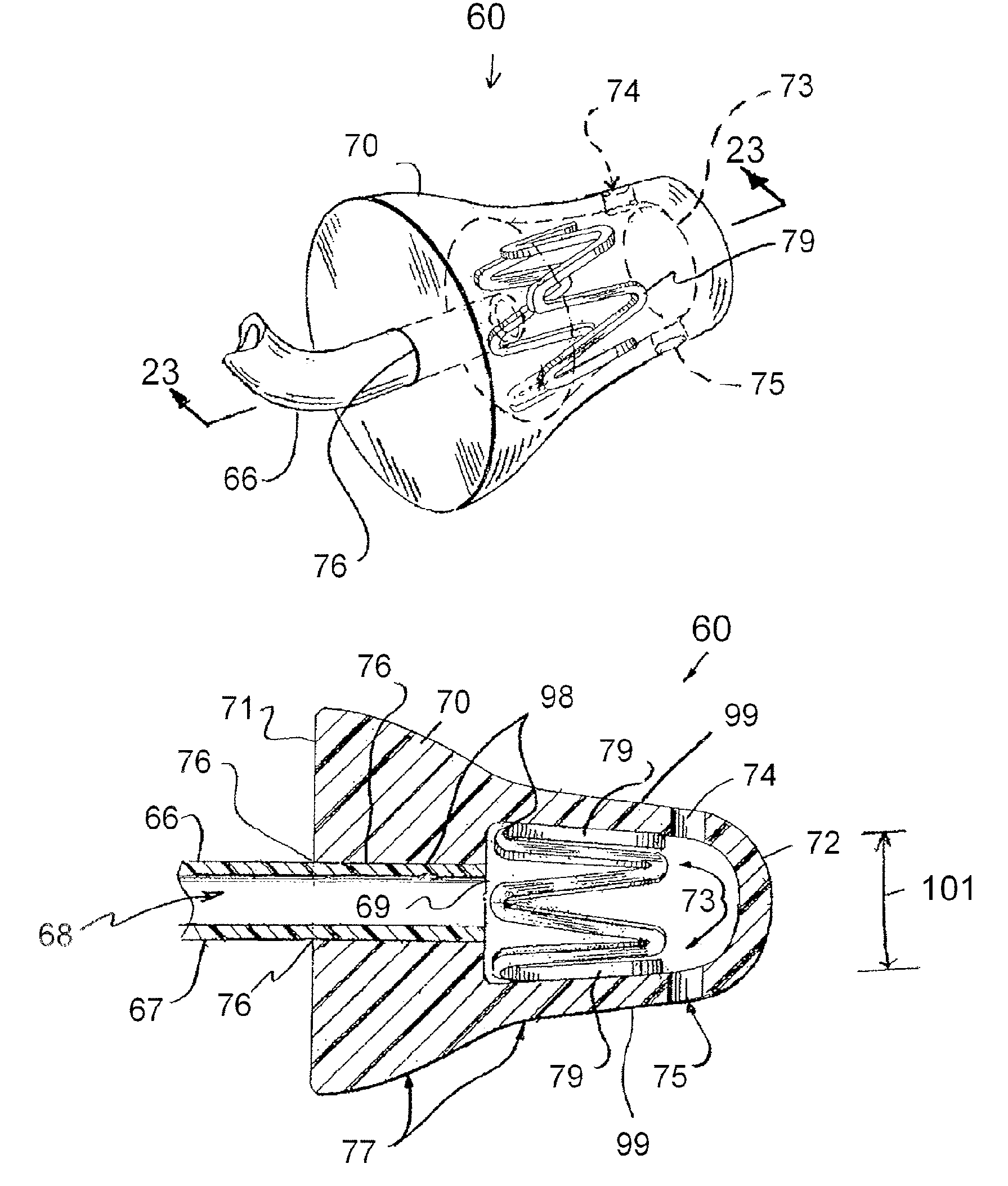
[0115]the apparatus of the present invention is shown in FIGS. 26-27, designated generally by the numeral 80. Hearing aid apparatus 80 provides an insert or plug 81 having a first end portion 82 and a second end portion 83. The second end portion 83 is positioned closest to a user's ear drum 97 when the insert or plug 81 is placed in the ear canal 63. Insert or plug 81 provides a cavity 84. A stent 79 is placed in cavity 84. Sound port openings 85, 86 communicate between the tapered outer surface 89 of insert or plug 81 and cavity 84. A third sound port opening such as 113 in FIG. 33 could be provided. Ear wax filter 114 could be provided between cavity 84 and any sound port opening 85, 86, 113 as shown in FIG. 33.

[0116]Socket 87 can be generally cylindrically shaped. The socket 87 extends between first end 82 of plug or insert 81 and cavity 84 as shown in FIG. 27. Socket 87 is receptive of speaker 88. The speaker 88 can be a commercially known speaker that is joined with wire cable...

fifth embodiment

[0119]FIG. 32 shows the apparatus of the present invention that employs an optional vent tube 112. In FIG. 32, vent tube 112 extends between cavity 73 and first end 71 as shown. In all other respects, the embodiment of FIGS. 32-33 can be the same as the preferred embodiment of FIGS. 22-25.

[0120]FIGS. 34-36 show yet another embodiment of the apparatus of the present invention, designated generally by the numeral 102. Hearing aid apparatus 102 provides an insert or plug 103 having first end 104 and second end 105. The insert 103 provides a cavity 106 next to the second end 105 as shown in FIG. 33. A pair of sound port openings 107, 108 communicate sound between cavity 106 and the area outside of plug 103.

[0121]Socket 109 can be generally cylindrically shaped and is receptive of tubing 66. An interference fit can be used for example to attach tube 66 to socket 109. Alternatively, tube 66 can be attached to insert or plug 103 at socket 109 using adhesive or other means known in the art ...


PUM


Abstract

A hearing aid body is provided that contains electronic hearing aid components and that is attachable to the user's body outside the ear canal. A conduit connects the hearing aid body to the flexible plug. The conduit enables sound emitted by the hearing aid to travel via the conduit to the flexible plug so that the user's able to hear a sound that is amplified by the hearing aid and received by the plug via the conduit. The conduit can be a flexible hollow tube or an electronic conduit that transmit electrical signals between the hearing aid and the plug. A stent embedded in the plug is provided, the stent having a first smaller diameter at a temperature below body temperature and being expandable to a second greater diameter when subjected to the user's body temperature, such as the temperature in the ear canal of a user.

Description

CROSS-REFERENCE TO RELATED APPLICATIONS[0001]Incorporated herein by reference are our U.S. Provisional Patent Application No. 60 / 762,429, filed 26 Jan. 2006, and our U.S. Provisional Patent Application No. 60 / 825,988, filed 18 Sep. 2006, priority of both of which is hereby claimed.[0002]Incorporated herein by reference are our International Application No. PCT / US2005 / 019046, filed 31 May 2005 (and re-published on 16 Mar. 2006 as International Publication No. WO 2005 / 120131 A2), our U.S. patent application Ser. No. 11 / 138,540, filed 26 May 2005 (published as US 2006-0098833 A1 on 11 May 2006), and our U.S. Provisional Patent Application No. 60 / 575,533, filed 28 May 2004.[0003]In the US, this is a continuation-in-part of International Application No. PCT / US2005 / 019046, filed 31 May 2005 and of U.S. patent application Ser. No. 11 / 138,540, filed 26 May 2005 now abandoned. In the US, priority of U.S. Provisional Patent Application No. 60 / 575,533, filed 28 May 2004, is hereby claimed.STAT...

Claims


Application Information

Patent Timeline
Patent Type & Authority Patents(United States)
IPC IPC(8): H04R25/00
CPCA61F11/10H04R25/652H04R25/658H04R25/656H04R25/456A61F2011/085H04R2460/15H04R25/659A61F11/085
Inventor JUNEAU, ROGER P.DESPORTE, EDWARD J.MAJOR, MICHAELSIEGLE, GREGORY R.TANNER, BRIAN
Owner GENERAL HEARING INSTR
Why Eureka
Try Eureka