Using energy-use sensors to model activity and location of building users

a technology of energy-use sensors and building users, applied in the field of household energy management, can solve the problems of excessive use of technology, large number of additional devices, complicated and costly hardware requirements for this system, etc., and achieve the effect of reducing energy costs for householders, increasing the background temperature of the house, and being cost-effectiv

Active Publication Date: 2010-08-17
CENTRICA HIVE LTD
View PDF13 Cites 93 Cited by
  • Summary
  • Abstract
  • Description
  • Claims
  • Application Information

AI Technical Summary

Benefits of technology

[0015]A model of the predicted behaviour of the occupants of a house allows more efficient use of the appliances in the house. For example, the predictive model may predict the times when the house will be occupied in order for the controller to control the operation of one or more household appliances, such as heating or cooling appliances, on the basis of the predicted times when the house will be occupied.
[0017]A model of the current behaviour of the occupants of a house also allows more efficient use of the appliances in the house. For example, the temporary model may allow the controller to control the operation of heating or cooling appliances to achieve a desired temperature according to the current level of activity of the occupants.
[0027]A household energy management system in accordance with the invention, which monitors the energy consumption of household appliances, can also act as an electricity meter and may indicate the electricity consumption reading to the householder or transmit the reading directly to the electricity provider. If the system is networked to the electricity provider, then the provider can inform the system of changing electricity prices. The system may simply inform the user of these prices or it may be programmed to control household appliances so as to minimize the energy costs to the householder. For example, it may be more cost-effective to increase the background temperature of the house by operating electrical heating appliances at a time of day when electricity is relatively cheap in order to reduce the amount of heating required when demand is at its peak. Alternatively, the electricity provider may be given direct control of the electrical heating appliances.
[0028]Similarly, if the system is networked to a gas supplier, then the supplier can inform the system of changing gas prices. The system may simply inform the user of these prices or it may be programmed to control household gas appliances, such as a gas-fired central heating boiler, so as to minimize the energy costs to the householder. Alternatively, the energy management system or the gas supplier itself may be given direct control of the gas supply via an electrically-operated gas valve.

Problems solved by technology

This large number of additional devices is complicated and costly.
The hardware requirements for this system seem excessive and expensive to retrofit into an existing household.
This appears an excessive use of technology with an extensive requirement for hardware and installation work by skilled electricians.
Many of these features will not be valued by householders who are happy to not have video cameras in the house.
The main financial saving to the householder is through improved temperature control and the additional systems seem excessive.
However, it relies on one control device being attached to one appliance to provide on / off control and this makes it an expensive system to retrofit.

Method used


Image

  • Using energy-use sensors to model activity and location of building users
  • Using energy-use sensors to model activity and location of building users
  • Using energy-use sensors to model activity and location of building users

Examples


Embodiment Construction
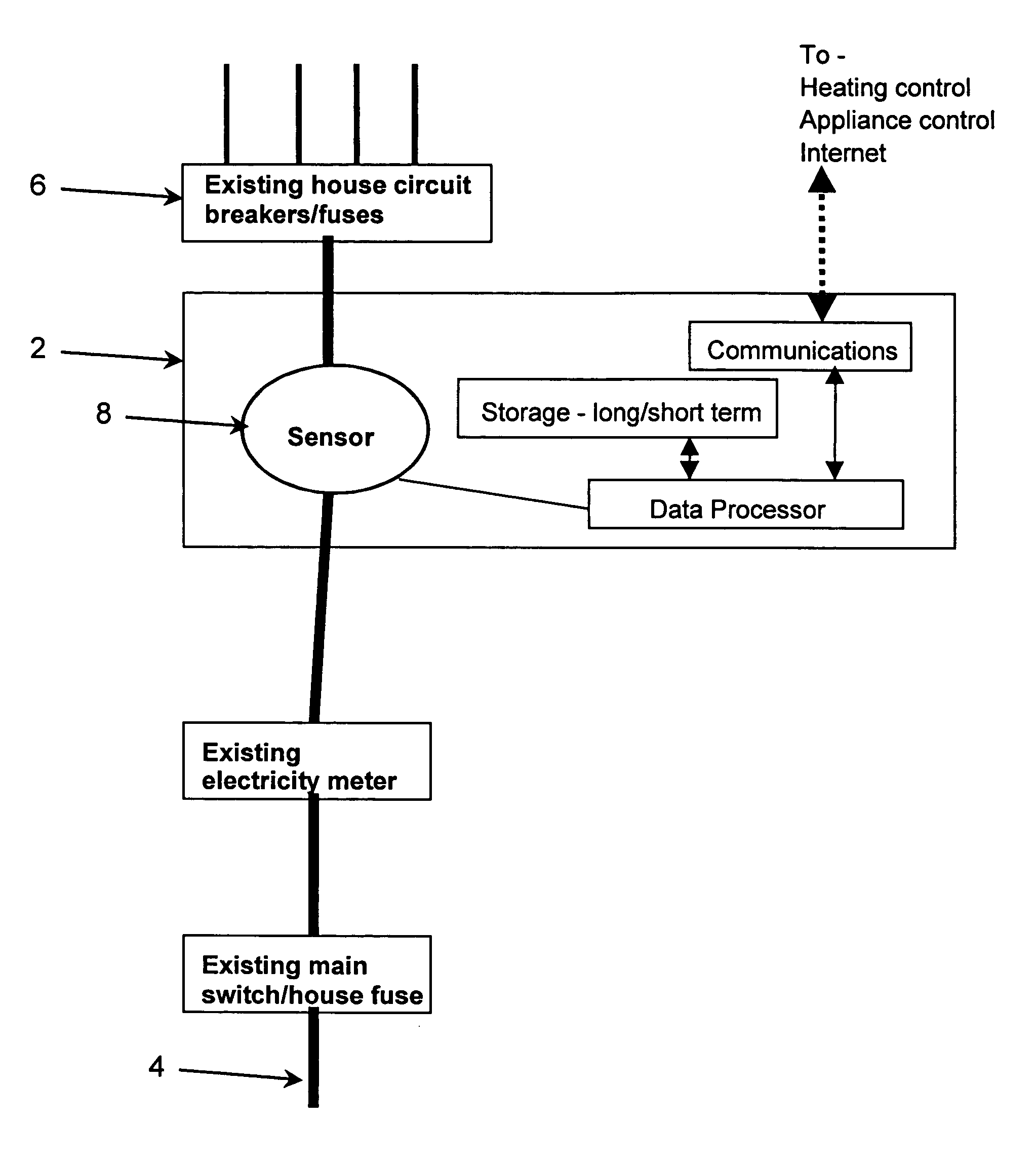
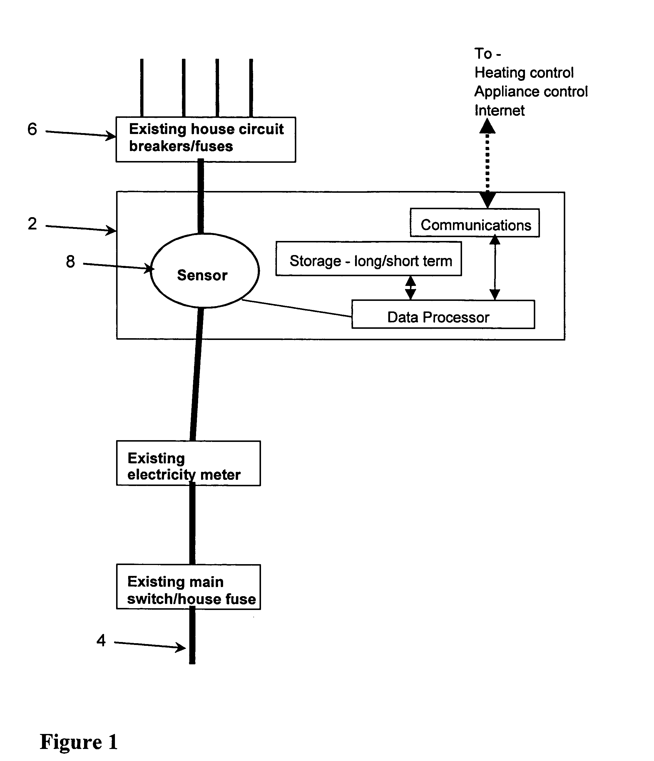
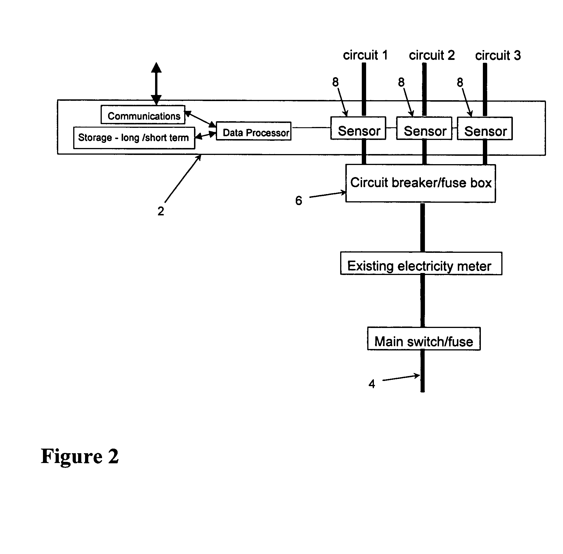
A Typical System

[0047]Consider a system, which uses a single central sensor to monitor the flow of electricity into the house. It records / analyses the data in great detail—not only on a minute by minute basis but also the instant an appliance is turned on it analyses the starting current in detail over milliseconds. In this way it determines which appliance has been turned on and how long it has been on for and at what time of day it has been used. It builds mathematical models of:[0048]All appliances used in the house and their pattern of use[0049]The house's transient thermal behaviour under heating and cooling conditions

[0050]The system is intended not just to monitor the electrical system or the gas heating system but to link the monitoring of gas and electricity together to allow a whole system understanding to be achieved and provide better optimisation of the total energy use within the house. For example, sudden changes in electrical activity can indicate that the householde...


PUM


Abstract

A household energy management system uses measurements of the household electricity supply to identify and to determine the energy consumption of individual household appliances. From these measurements, models can be built of the behaviour of the occupants of the house, the thermal properties of the house and the efficiency of the appliances. Using the models, the household appliances—in particular heating and cooling appliances—can be controlled to optimize energy efficiency; and maintenance programmes for the appliances and for the house itself can be recommended to the householder or arranged with a service company.

Description

[0001]This U.S. patent application claims foreign priority benefits under 35 U.S.C. 119 of British Application No. 0327583.1, dated Nov. 27, 2003.TECHNICAL FIELD OF THE INVENTION[0002]The invention relates to the field of household energy management and in particular to ways in which the behaviour of the occupants of a house, the thermal properties of the house and the operation of household appliances can be measured and modelled, in order to control the household appliances in a certain way or to recommend courses of action to the users of the system such that energy use by the household is made more efficient.[0003]Throughout this specification, the words “house” and “household” are used for convenience but those words are not to be interpreted as limiting the scope of the invention to the context of separate, domestic dwellings. Among other things, the word “house” is intended to include within its scope an apartment, an office, a hotel room or a part of any of the aforesaid.BAC...

Claims


Application Information

Patent Timeline
Patent Type & Authority Patents(United States)
IPC IPC(8): G05B13/02G05B23/02
CPCG05B15/02G05B2219/2642
Inventor OSWALD, JAMES IANTAMSETT, STEPHEN JOHN
Owner CENTRICA HIVE LTD
Why Eureka
Try Eureka