Method and system for local load control

a load control and load technology, applied in adaptive control, static/dynamic balance measurement, instruments, etc., can solve the problems of increasing the complexity of the infrastructure for generating and delivering energy, the inability to perfectly align the various components, and the unusually large amount of energy consumers demand for heating or cooling

Active Publication Date: 2010-08-17
ITRON
View PDF57 Cites 41 Cited by
  • Summary
  • Abstract
  • Description
  • Claims
  • Application Information

AI Technical Summary

Problems solved by technology

As utilities have become deregulated, the infrastructure for generating and delivering energy has become more complex.
A problem with this multi-party network is that the various components may not be perfectly in sync at all times. During extremely hot or extremely cold weather, for example, consumers may demand unusually large amounts of energy for heating or cooling.
It is possible that either the generator will not be able to produce sufficient energy, or that the transmission or distribution network will not be able to accommodate sufficient energy.

Method used


Image

  • Method and system for local load control
  • Method and system for local load control
  • Method and system for local load control

Examples


Embodiment Construction

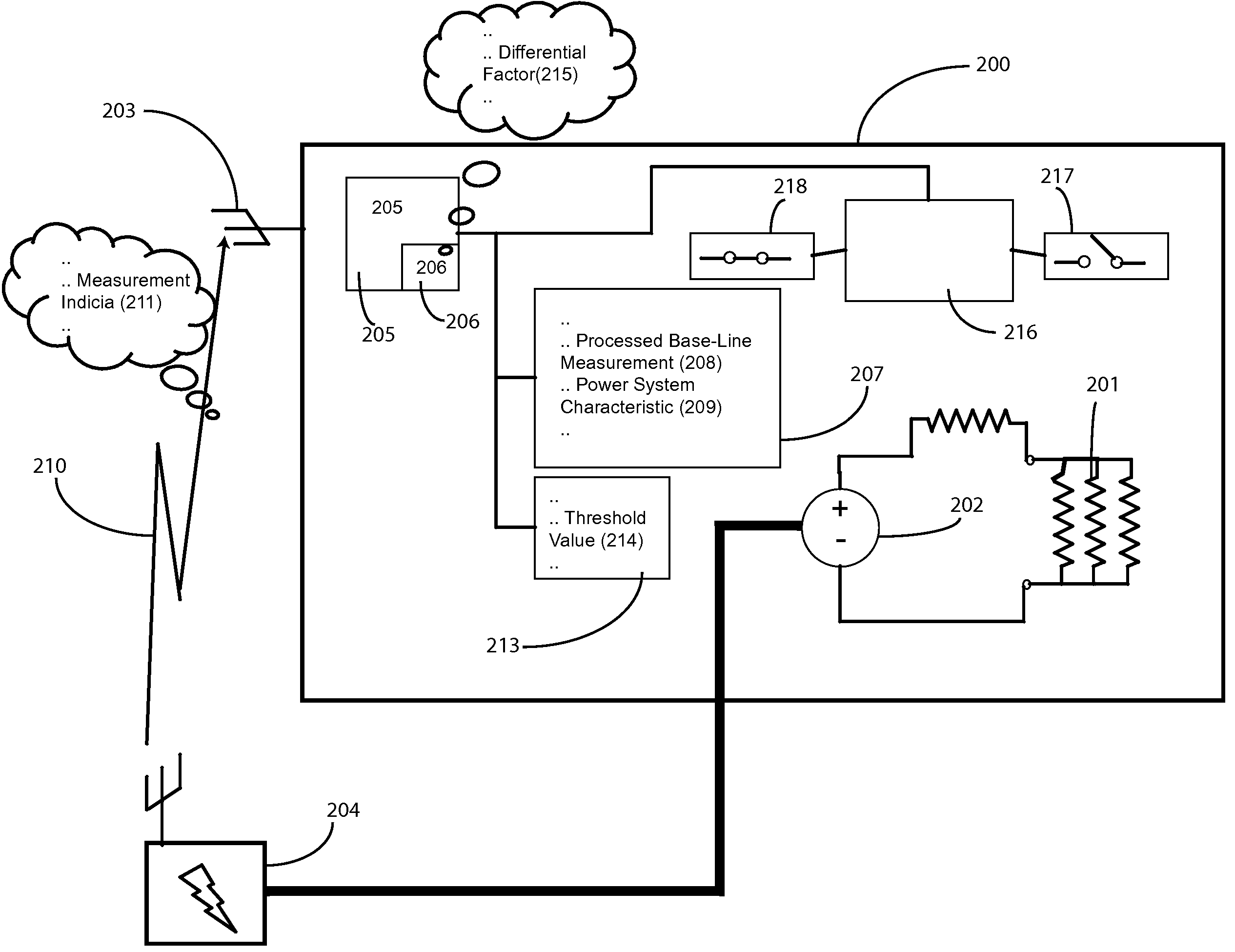
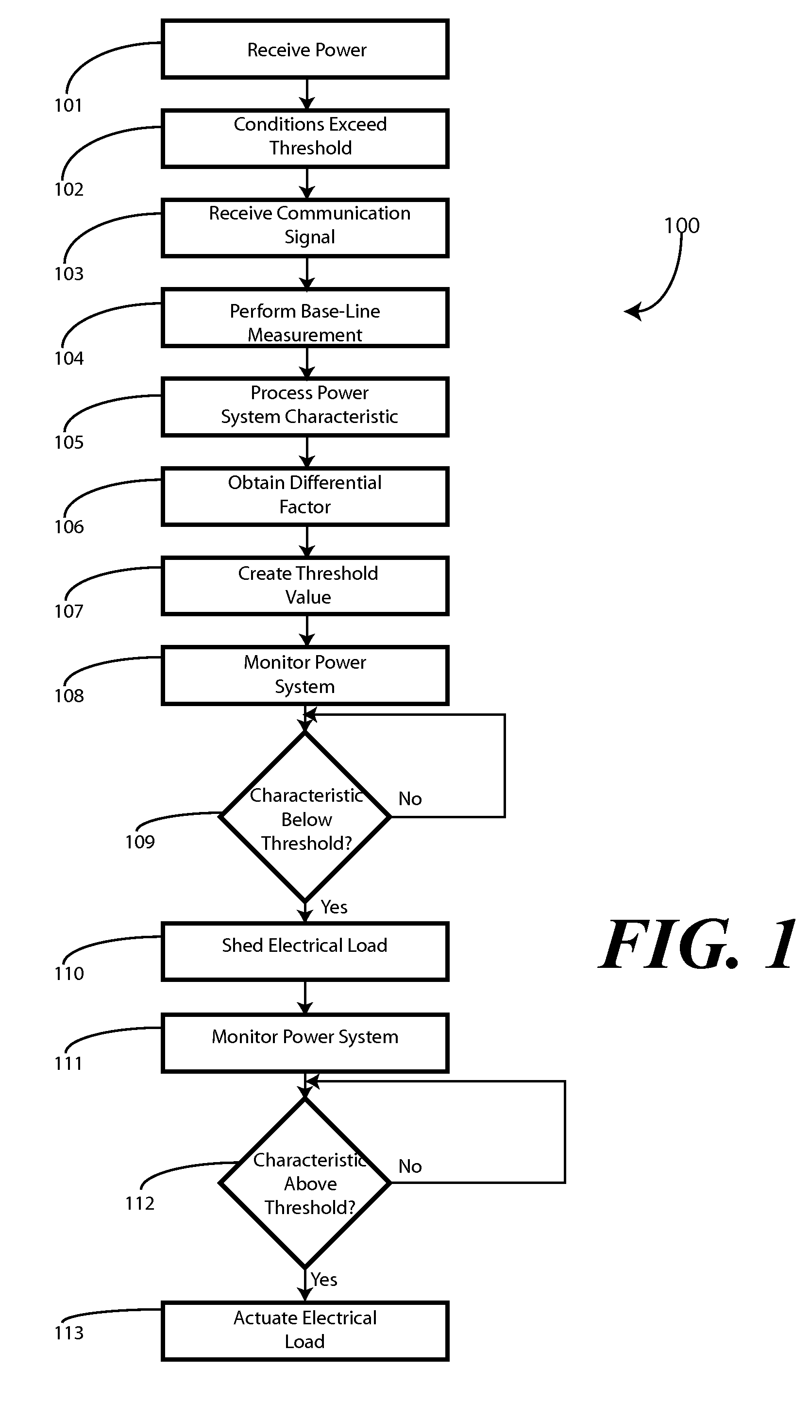
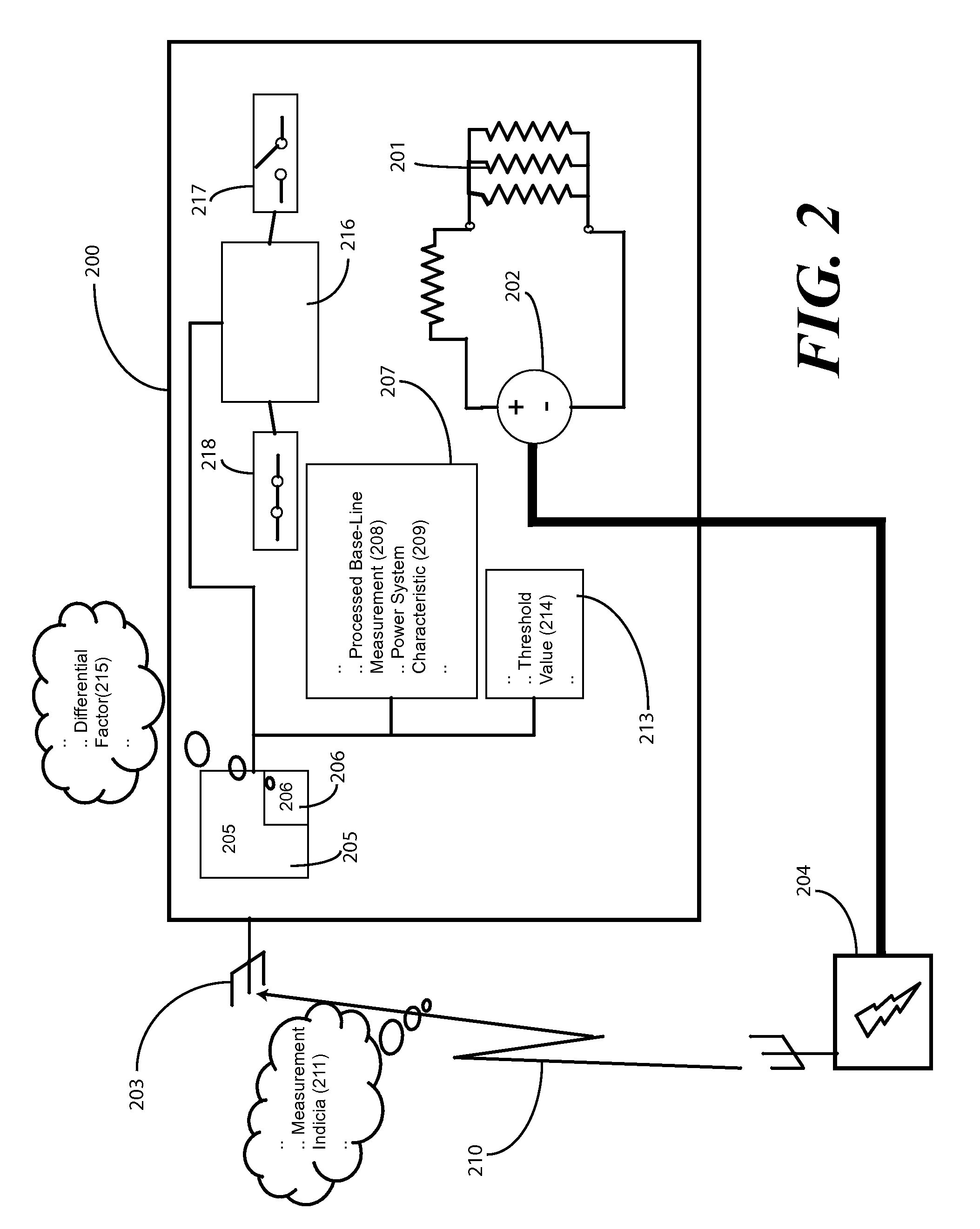
[0013]Before describing in detail embodiments that are in accordance with the present invention, it should be observed that the embodiments reside primarily in combinations of method steps and apparatus components related to control a load device when a source voltage falls below a baseline established at a predetermined time. Accordingly, the apparatus components and method steps have been represented where appropriate by conventional symbols in the drawings, showing only those specific details that are pertinent to understanding the embodiments of the present invention so as not to obscure the disclosure with details that will be readily apparent to those of ordinary skill in the art having the benefit of the description herein.

[0014]It will be appreciated that embodiments of the invention described herein may be comprised of one or more conventional processors and unique stored program instructions that control the one or more processors to implement, in conjunction with certain ...


PUM


Abstract

A method and system for shedding loads based upon a power system characteristic, such as voltage or frequency, is provided. In one embodiment, a remote party, such as a power generator or utility, transmits a signal to a control device proximately located with a load device. Upon receipt of the signal, the control device measures the power system characteristic for a predetermined time to establish a baseline threshold. The control device then monitors the power system characteristic. When the power system characteristic falls outside the baseline threshold, the control device sheds load. In one embodiment, the loads are prioritized such that the load of least importance may be shed first.

Description

CROSS REFERENCE TO PRIOR APPLICATIONS[0001]This application claims priority and benefit under 35 U.S.C. §119(e) from U.S. Provisional Application No. 60 / 714,801, filed Sep. 7, 2005, which is incorporated by reference for all purposes.BACKGROUND[0002]1. Technical Field[0003]This invention relates generally to load control systems, and more specifically to a method and apparatus for reducing an operating time of a load, such as an air compressor or furnace, when a source voltage falls below a base line established during a predetermined time.[0004]2. Background Art[0005]As utilities have become deregulated, the infrastructure for generating and delivering energy has become more complex. A generator produces energy and delivers it to s transmission grid. The owner of the transmission grid then “wheels” the energy to a distribution network. The owner of the distribution network then delivers it to an end user. The generator then bills the end user. The generator then pays the transmissi...

Claims


Application Information

Patent Timeline
Patent Type & Authority Patents(United States)
IPC IPC(8): G05D3/12G05D9/00G05D5/00
CPCH02J3/14Y02B70/3225Y04S20/222H02J2310/60
Inventor ROSSI, JOHN F.NG, HOWARD
Owner ITRON
Why Eureka
Try Eureka