
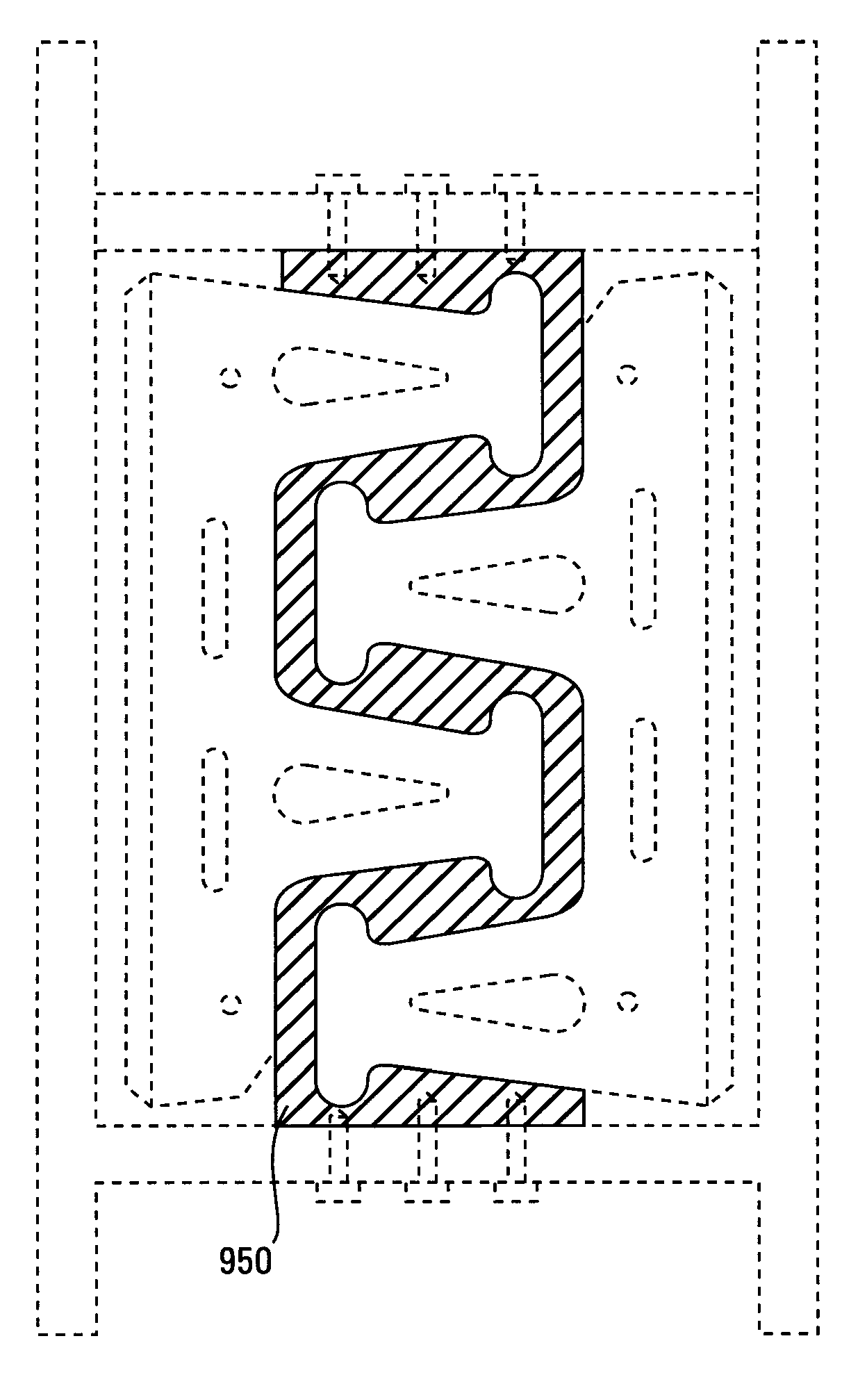
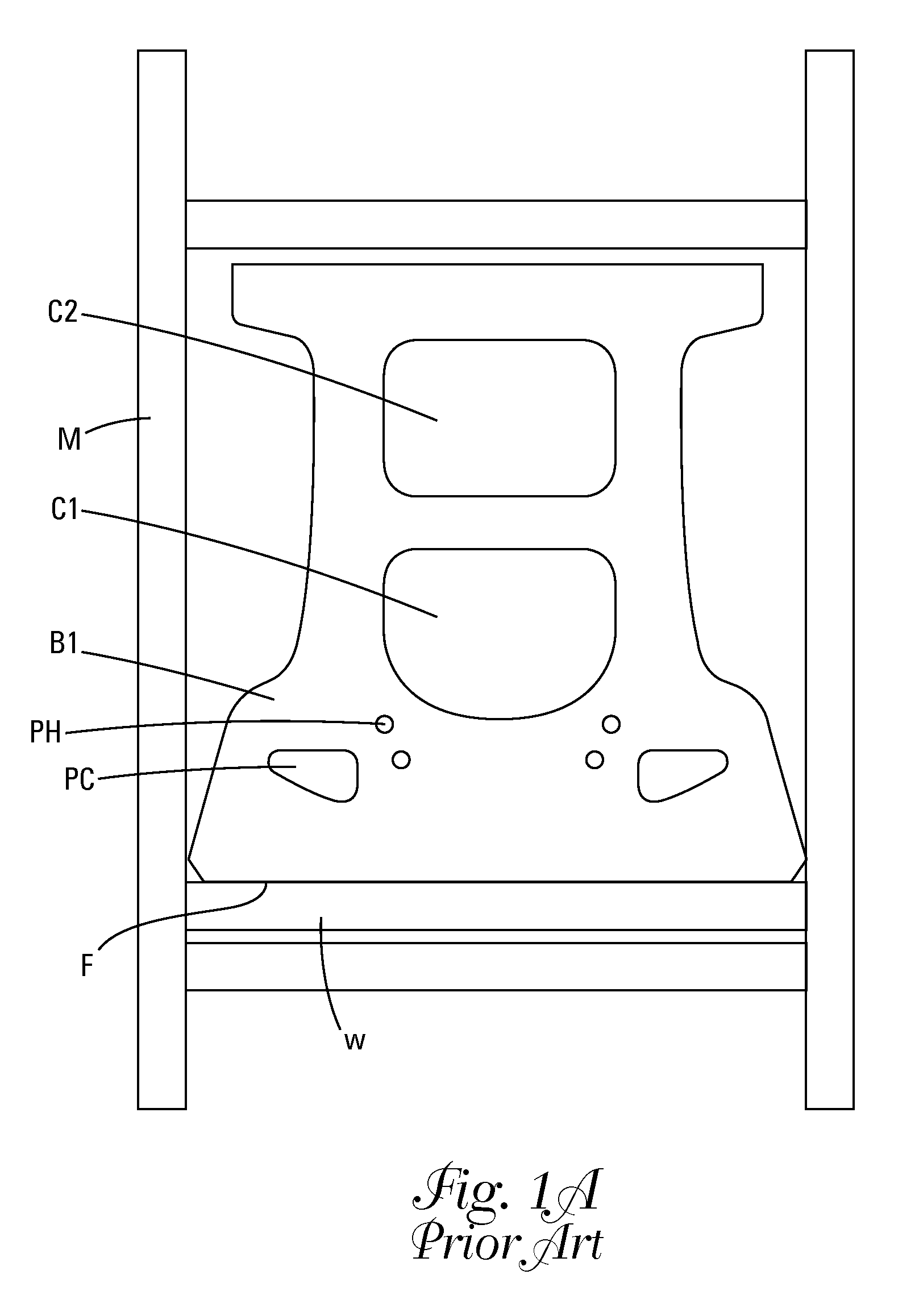
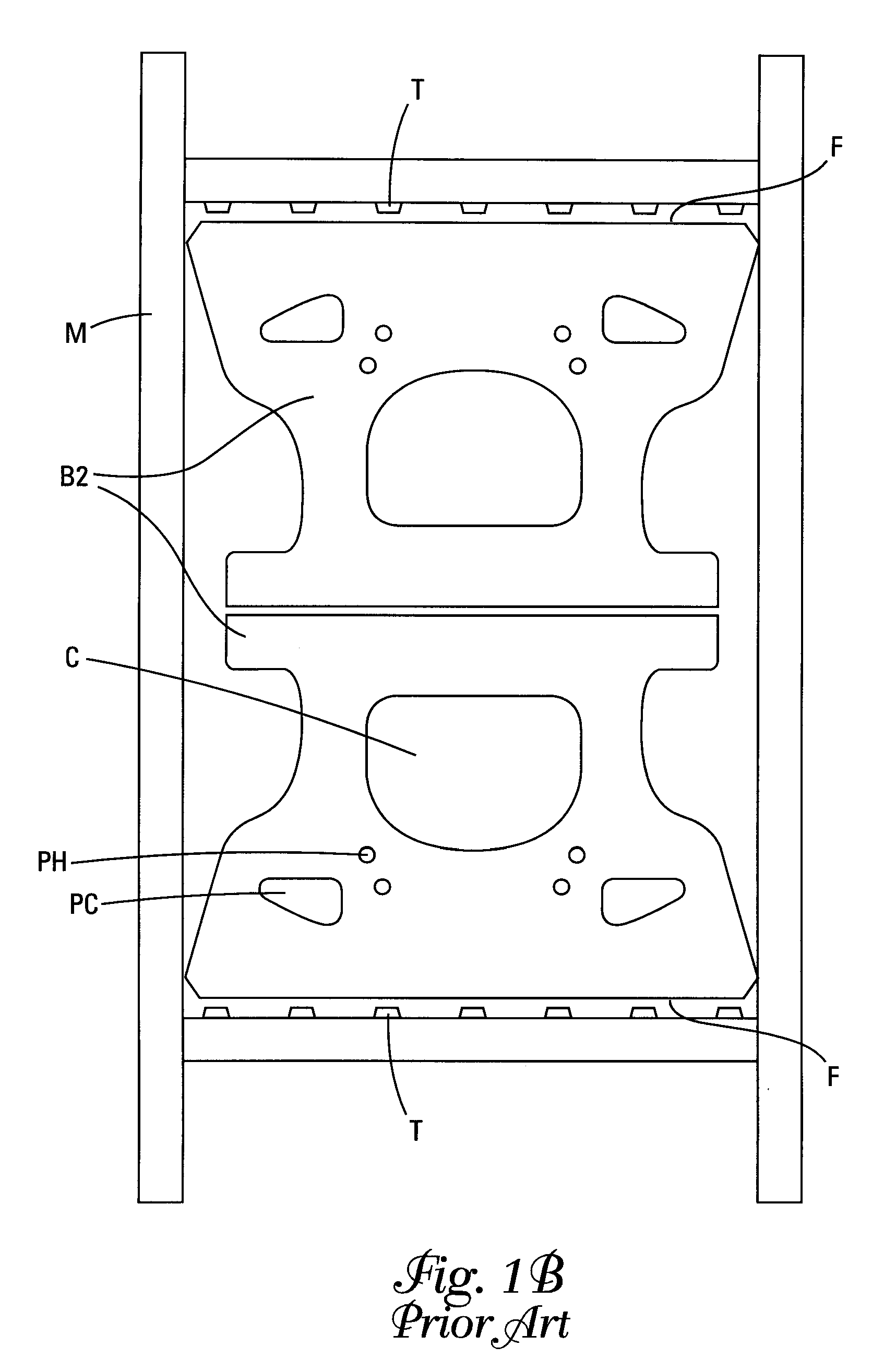
Mold box for making first and second wall blocks

a mold box and wall block technology, applied in manufacturing tools, applications, lighting and heating apparatus, etc., can solve the problem of block weight of about 250 lbs (113.6 kg), and achieve the effect of maximizing the use of the mold box, large surface area, and convenient handling

Inactive Publication Date: 2010-08-24
KEYSTONE RETAINING WALL SYST
View PDF68 Cites 34 Cited by
  • Summary
  • Abstract
  • Description
  • Claims
  • Application Information

AI Technical Summary

Benefits of technology

"The present invention is a mold box and a method of making wall blocks that maximize the use of the mold box and produce lightweight and easy-to-handle wall blocks. The mold box has a larger front face surface area than blocks made using other methods, resulting in faster construction and higher production yields. The method of making wall blocks involves dividing the mold cavity into two sections, each optimized for forming a different block, and filling each section with desired block material before removing the material from the mold. The resulting wall blocks have a large front face surface area and are lightweight and easy-to-handle."

Problems solved by technology

However, this block weighs about 250 lbs (113.6 kg) and must be set in place using mechanized means.

Method used


Image

  • Mold box for making first and second wall blocks
  • Mold box for making first and second wall blocks
  • Mold box for making first and second wall blocks

Examples


Embodiment Construction

[0042]In this application, “upper” and “lower” refer to the placement of the block in a retaining wall. The lower surface faces down, that is, it is placed such that it faces the ground. In forming a retaining wall, one row of blocks is laid down, forming a course. A second course is laid on top of this by positioning the lower surface of one block on the upper surface of another block.

[0043]The blocks of this invention may be made of a rugged, weather resistant material, such as concrete, especially if the wall is constructed outdoors. Other suitable materials include plastic, reinforced fibers, and any other materials suitable for use in molding wall blocks. The surface of the blocks may be smooth or may have a roughened appearance, such as that of natural stone. The blocks are formed in a mold and various textures can be formed on the surface, as is known in the art.

[0044]Several embodiments are illustrated in the figures below. In one embodiment, this invention is a block compri...


PUM

PropertyMeasurementUnit
distance d2aaaaaaaaaa
distance d3aaaaaaaaaa

Abstract

A method of making a wall block and a mold box therefore. The wall block design maximizes the use of the mold box. The method produces wall blocks having a large surface area front face compared to the front face size of prior art blocks. The blocks have about one third more front surface area. This results in faster construction of walls and a faster construction sequence. The method of making the blocks makes efficient use of mold space and material, resulting in higher production yields and / or higher total daily production square footage.

Description

[0001]This application is a continuation-in-part of application Ser. No. 29 / 186,712, filed Jul. 21, 2003, now U.S. Pat. No. Des. 501,935 hereby incorporated herein by reference.FIELD OF THE INVENTION[0002]The present invention relates to retaining wall blocks and a method for making these blocks.BACKGROUND OF THE INVENTION[0003]Numerous methods and materials exist for the construction of retaining walls. Such methods include the use of natural stone, poured in place concrete, masonry, and landscape timbers or railroad ties. In recent years, segmental concrete retaining wall units which are dry stacked (i.e., built without the use of mortar) have become a widely accepted product for the construction of retaining walls. Such products have gained popularity because they are mass produced, and thus relatively inexpensive. They are structurally sound, easy and relatively inexpensive to install, and couple the durability of concrete with the attractiveness of various architectural finishe...

Claims


Application Information

Patent Timeline
Patent Type & Authority Patents(United States)
IPC IPC(8): B28B7/24E02D29/02E04C1/39
CPCB28B7/241E02D29/025E04C1/395B28B7/24B28B7/00E02D29/02E04C1/39
Inventor DAWSON, WILLIAM B.MACDONALD, ROBERT A.
Owner KEYSTONE RETAINING WALL SYST
Learn More