Method to produce a curved coil, in particular a sub-coil of a gradient coil for a magnetic resonance apparatus

a technology of gradient coil and sub-coil, which is applied in the direction of magnets, magnetic bodies, instruments, etc., can solve the problems of unusable coils and the operation of gradient coils, and achieve the effect of simple manufacturing and cost-effectiveness

Inactive Publication Date: 2010-08-24
SIEMENS HEALTHCARE GMBH
View PDF10 Cites 2 Cited by
  • Summary
  • Abstract
  • Description
  • Claims
  • Application Information

AI Technical Summary

Benefits of technology

[0005]An object of the present invention is to provide a method that enables the production of a curved coil in a simple manner without the aforementioned problems.
[0010]As described, it is possible to use band-shaped detector elements, wherein multiple such fixing element bands can also be used depending on the size of the conductor pattern. These can now be attached in arbitrary position or, respectively, arrangement relative to one another on the pre-curved conductor or conductors provided on the plate side. For example, a star-shaped pattern is possible in the production of fingerprint coils. The possibility also exists to attach the fixing element bands in selected positions—for example where multiple conductor loops run relatively closely adjacent to one another—in order to be able to cover as many conductors as possible with one fixing band. The use of such relatively narrow fixing bands is advantageous since a very good perfusion of the coil structure with casting resin in production and casting of a gradient coil is hereby enabled, and the heat transfer can be improved because a relatively large area is not occupied by the insulating fixing element. This means that the cooling of a gradient coil is improved; higher powers are possible given the same maximum temperature.
[0014]Before the wrapping of the conductor on the winding plate, the tightening strap or tightening straps are advantageously placed in this; for example, a groove running transversely to the pivot direction of the individual plate elements relative to one another and serving to accommodate the tightening strap is provided for this. The conductor is thus wound around the tightening strap; this lies underneath the conductor. In the installation situation on the winding spindle, it is then located on the outside of the conductor so that this can be tensioned and fixed in a simple manner.
[0018]The mobility of the plate elements relative to one another can be achieved in different ways. According to a first embodiment of the invention, two plate elements can be connected with one another via an articulation (hinge joint) to enable the relative movement. Such an articulation can be formed by two bearing lugs situated adjacent to one another that are penetrated by an axle bolt. A bolt hinge or shaft hinge effectively results.
[0021]As an alternative to producing the relative mobility by an articulation, two plate elements can be connected with one another by a flexible connection element such that they can move relative to each other. Such a connection element is, for example, a metal band that is permanently connected (in particular welded) with both plate elements, the metal band advantageously extending across all plate elements. Such a metal band (for example made from spring steel) offers a sufficient mobility of the plate elements relative to one another, however also sufficiently securely fixes these. In this case the plate are made from metal, but they can also be made from plastic, in which case the metal band is then bolted to the individual plate elements, for example. This offers the possibility to use plate elements produced in a simple extrusion method, which plate elements are merely to be processed to form a winding plate with articulations. Overall this makes the manufacture of the articulated winding plate simple and cost-effective.

Problems solved by technology

High shearing strains, which place high demands on the bonding and shear resistance of the employed adhesive as well as the support plate itself, thereby occur between the conductor and the support plate.
These high shearing strains can now lead to the situation that the adhesion locally detaches in the forming, or detaches at a later point in time due to the high strain load, which either makes the sub-coils unusable or leads to problems in the operation of the gradient coil after integration into the gradient coil has already occurred.

Method used


Image

  • Method to produce a curved coil, in particular a sub-coil of a gradient coil for a magnetic resonance apparatus
  • Method to produce a curved coil, in particular a sub-coil of a gradient coil for a magnetic resonance apparatus
  • Method to produce a curved coil, in particular a sub-coil of a gradient coil for a magnetic resonance apparatus

Examples


Embodiment Construction

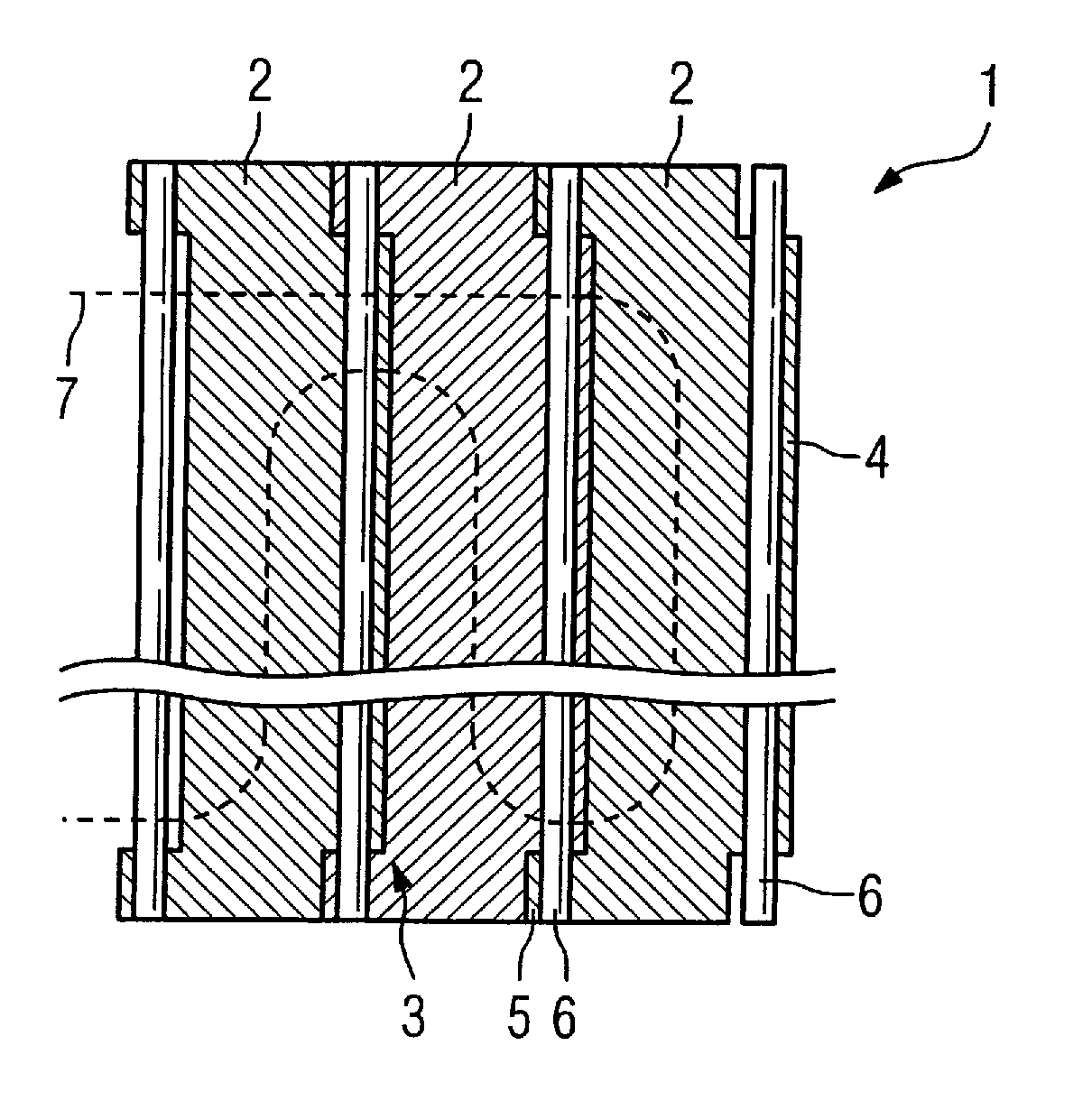
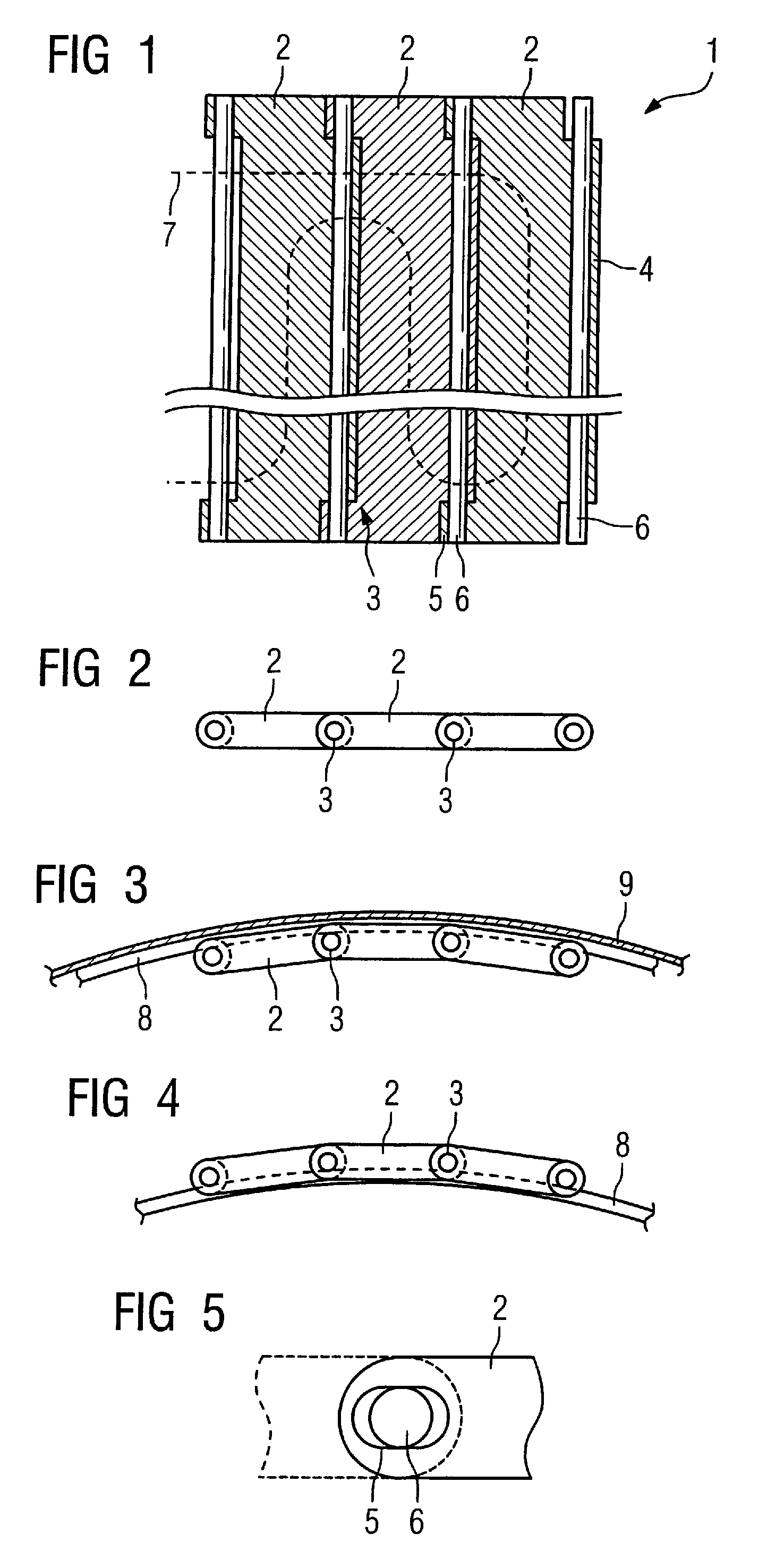
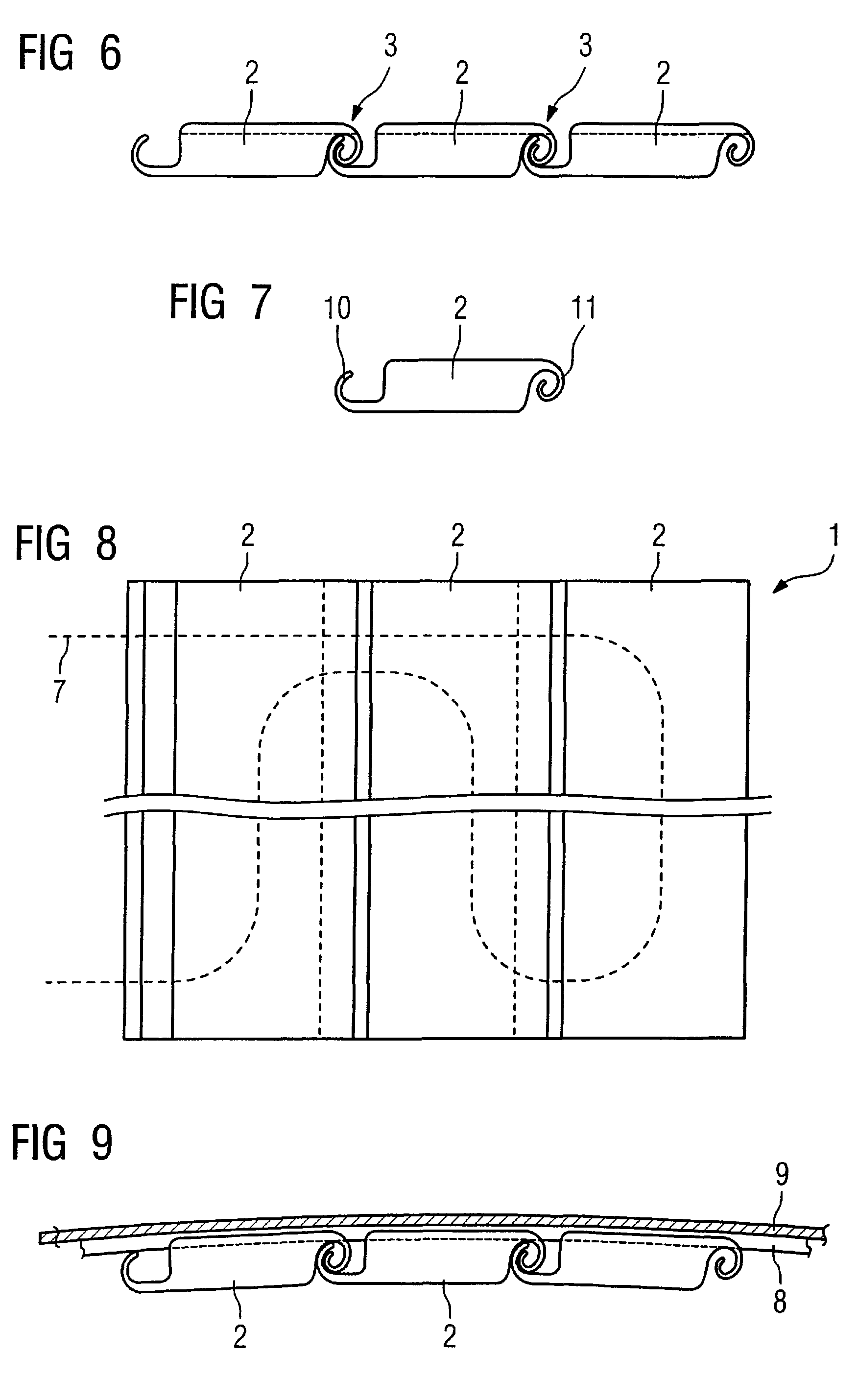
[0037]FIG. 1 shows a winding plate 1 according to the invention, consisting of multiple rectangular plate elements 2 made from metal or plastic. The more plate elements 2 that are provided, the better that a rounded, curved shape can be achieved. The individual plate elements 2 are connected with one another such that they can pivot via articulations 3 in the region of their adjacent longitudinal edges. At every plate element a first bearing lug 4 is provided on the one side and two bearing lugs 5 are respectively provided on the other side (there at the ends). The bearing lugs 4 and 5 engage in one another and are penetrated by an axle or shaft 6 to form the articulation, which is shown in the section view in FIG. 1. The two bearing lugs 5 are therefore executed somewhat oblong (see FIG. 5) so that a transverse mobility of two adjacent plate elements 2 is possible, meaning that these can vary somewhat in their separation in order to enable a longitudinal compensation. The two plate...


PUM

PropertyMeasurementUnit
electricalaaaaaaaaaa
shapeaaaaaaaaaa
diameteraaaaaaaaaa

Abstract

In a method to produce a curved coil, in particular a sub-coil of a gradient coil for a magnetic resonance apparatus, at least one conductor is wound corresponding to a predetermined pattern on a winding plate, and a winding plate composed of multiple plate elements that are moveable relative to one another is used that is formed into a curved shape after the winding of the conductor, in which curved shape the conductor is fixed while maintaining the curved shape.

Description

BACKGROUND OF THE INVENTION[0001]1. Field of the Invention[0002]The present invention concerns a method to produce a curved coil, in particular a sub-coil of a gradient coil for a magnetic resonance apparatus as well as a winding plate for use in this method.[0003]2. Description of the Prior Art[0004]Large-area coils, for example sub-coils of a gradient coil of a magnetic resonance apparatus, are typically produced by introducing a wire of one or multiple millimeters in diameter into the groove of a winding plate. In the case of a gradient sub-coil, the groove path corresponds to a predetermined pattern that in turn is designed with regard to the magnetic fields to be generated by means of the sub-coils. After wrapping the conductor, which protrudes slightly from the groove in the wrapped position, a support plate is typically placed upon it that is firmly connected with the conductor by an adhesive layer. Because gradient coils are typically cylindrical coils, it is necessary to be...

Claims


Application Information

Patent Timeline
Patent Type & Authority Patents(United States)
IPC IPC(8): H01F27/30H01F7/06H01F5/00
CPCG01R33/385G01R33/3858H01F41/0687H01F41/065Y10T29/49073H01F41/071H01F41/098
Inventor KOLBECK, THOMASSCHUSTER, JOHANNSCHOEN, LOTHARSTOCKER, STEFAN
Owner SIEMENS HEALTHCARE GMBH
Why Eureka
Try Eureka