

Method to produce a curved coil, in particular a sub-coil of a gradient coil for a magnetic resonance apparatus
- Summary
- Abstract
- Description
- Claims
- Application Information
AI Technical Summary
Benefits of technology
Problems solved by technology
Method used
Image

Examples
Embodiment Construction
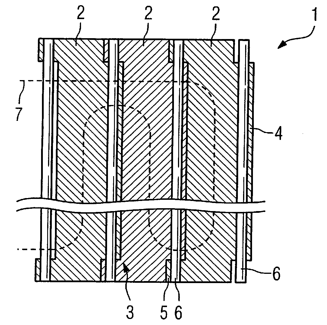
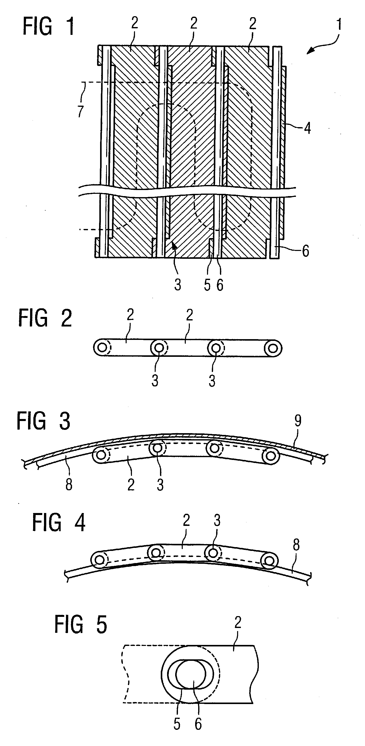
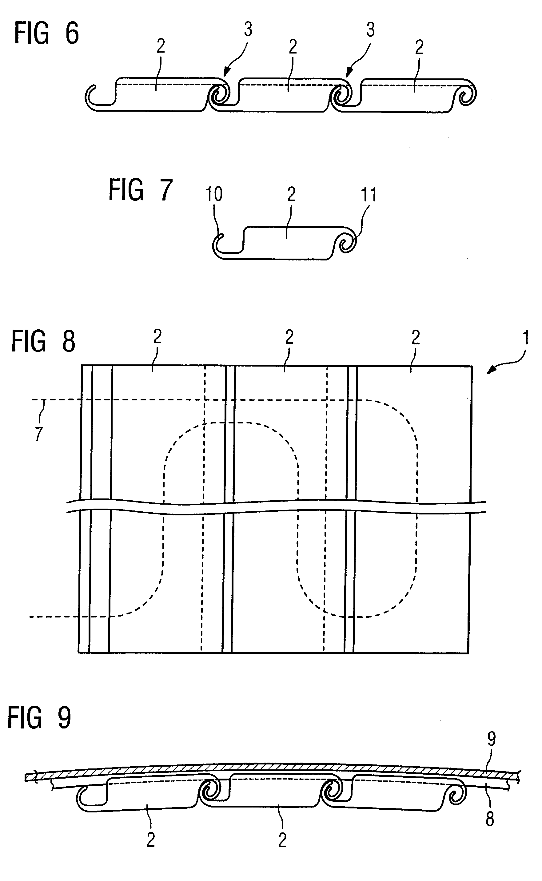
[0037]FIG. 1 shows a winding plate 1 according to the invention, consisting of multiple rectangular plate elements 2 made from metal or plastic. The more plate elements 2 that are provided, the better that a rounded, curved shape can be achieved. The individual plate elements 2 are connected with one another such that they can pivot via articulations 3 in the region of their adjacent longitudinal edges. At every plate element a first bearing lug 4 is provided on the one side and two bearing lugs 5 are respectively provided on the other side (there at the ends). The bearing lugs 4 and 5 engage in one another and are penetrated by an axle or shaft 6 to form the articulation, which is shown in the section view in FIG. 1. The two bearing lugs 5 are therefore executed somewhat oblong (see FIG. 5) so that a transverse mobility of two adjacent plate elements 2 is possible, meaning that these can vary somewhat in their separation in order to enable a longitudinal compensation. The two plate...
PUM
| Property | Measurement | Unit |
|---|---|---|
| Angle | aaaaa | aaaaa |
| Electrical conductivity | aaaaa | aaaaa |
| Flexibility | aaaaa | aaaaa |
Abstract
Description
Claims
Application Information