
System, methods and apparatus for cerebral protection

a technology of cerebral protection and system, applied in the field of medical devices, can solve the problems of reduced oxygen and nutrients to tissues, reduced cerebral perfusion, and neurological deficit of patients with cerebral ischemia, so as to reduce the risk of ischemic damage, inhibit or minimize tissue damage, and maintain and/or improve cerebral perfusion.

Active Publication Date: 2014-01-14
YACOUBIAN VAHE STEPHAN +1
View PDF22 Cites 4 Cited by
  • Summary
  • Abstract
  • Description
  • Claims
  • Application Information

AI Technical Summary

Benefits of technology

This approach effectively maintains or increases cerebral perfusion, reduces neural tissue damage, and extends the safe duration for interventional procedures by ensuring better brain protection during ischemic events, as demonstrated by clinical results showing universal cerebral protection with minimal neurologic deficits.

Problems solved by technology

Patients experiencing cerebral ischemia often suffer from disabilities ranging from transient neurological deficit to irreversible damage (stroke) or death.
Shock is the state in which failure of the circulatory system to maintain adequate cellular perfusion results in reduction of oxygen and nutrients to tissues.
Anoxic brain injury results in permanent neural tissue death after only as little as five minutes in normothermic conditions.

Method used


Image

  • System, methods and apparatus for cerebral protection
  • System, methods and apparatus for cerebral protection
  • System, methods and apparatus for cerebral protection

Examples


first embodiment

III. First Embodiment

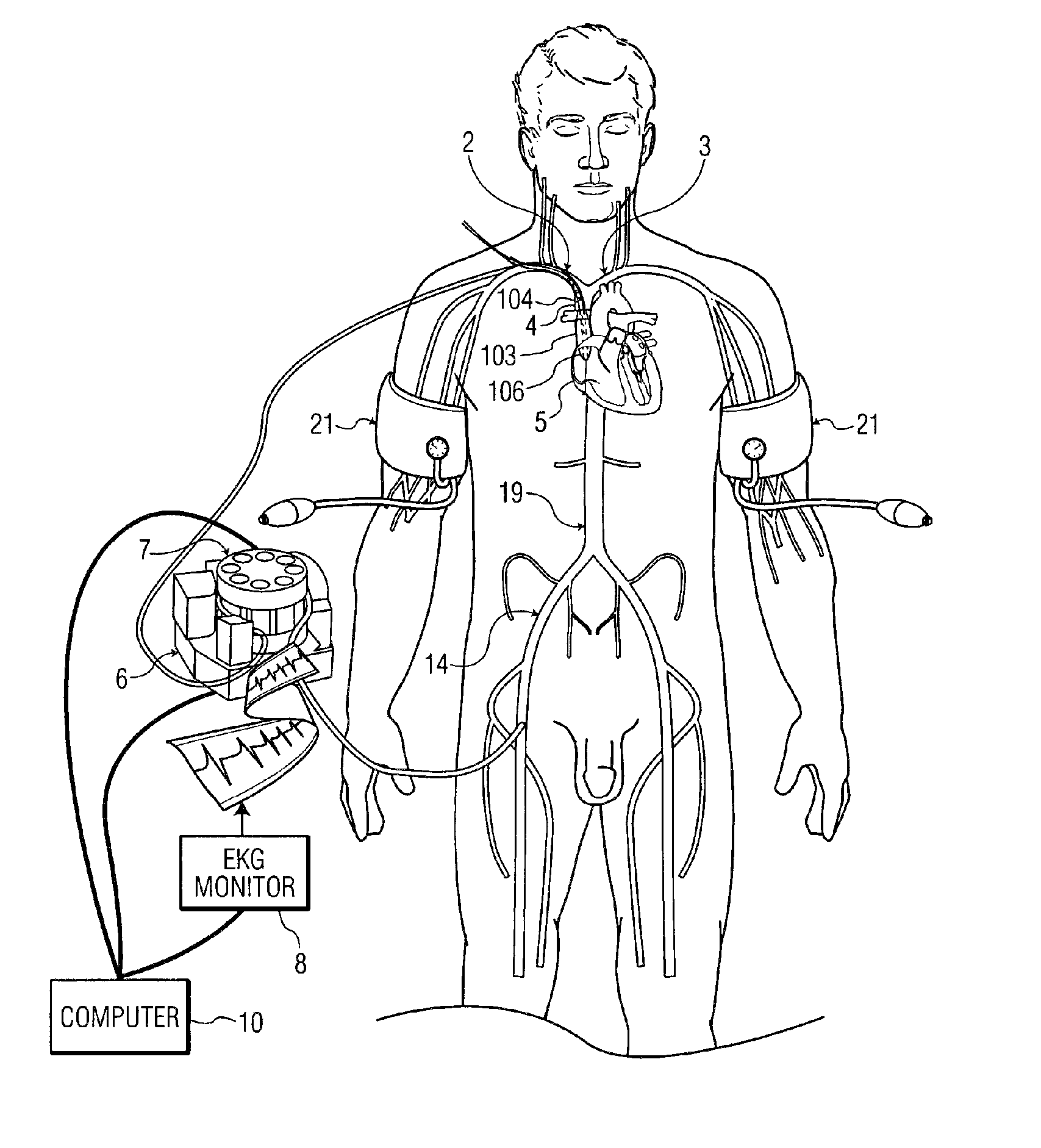
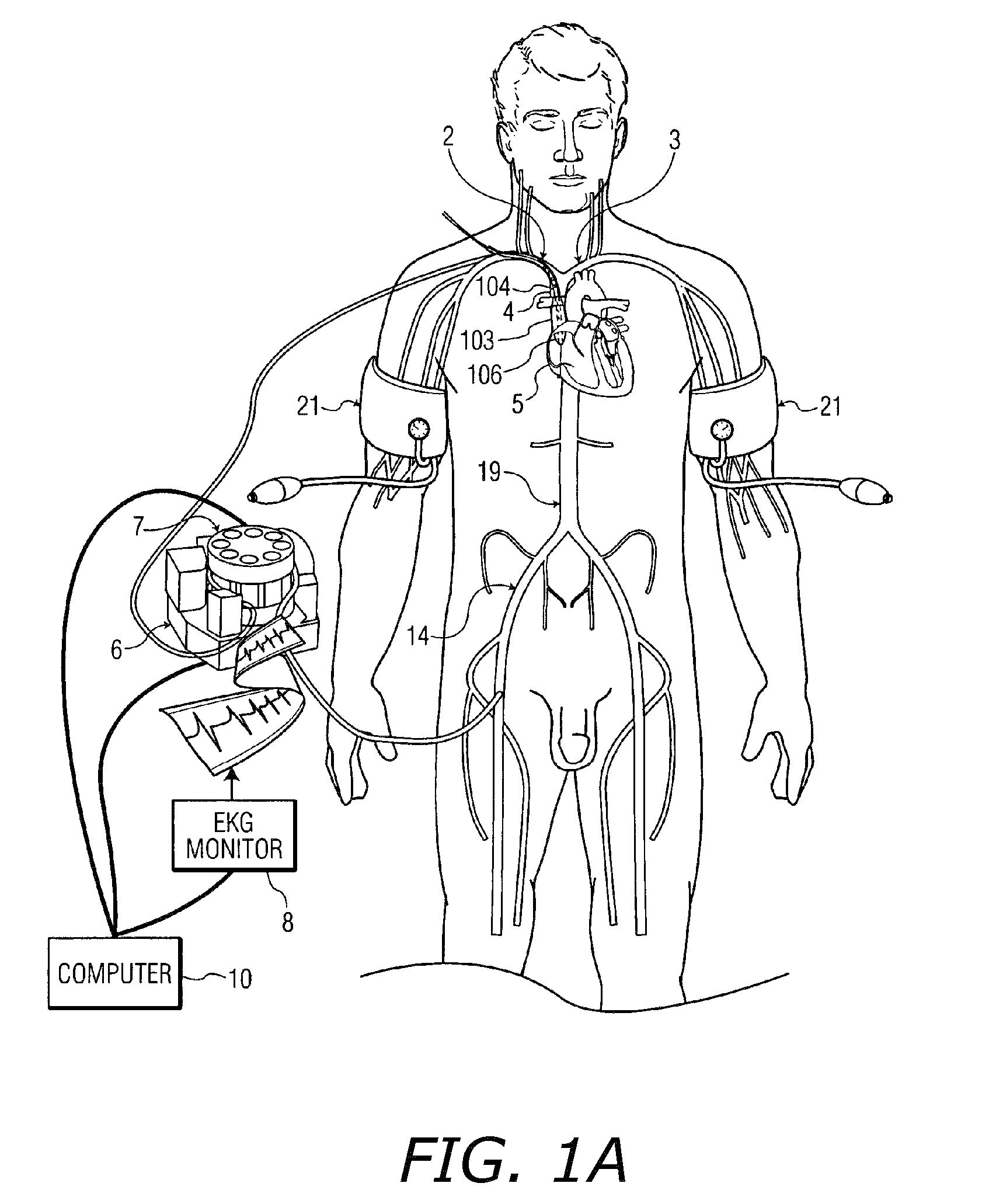
[0083]The present embodiment describes a method and system for selectively perfusing the brain with retrograde cold blood during acute cessation of perfusion to a specific area of the brain due to closure or lack of flow in the arterial blood supply to that segment. It is noted that in the embodiments described throughout the specification, the various methods may utilize the left subclavian vein or the right subclavian vein with equal efficacy of operation.

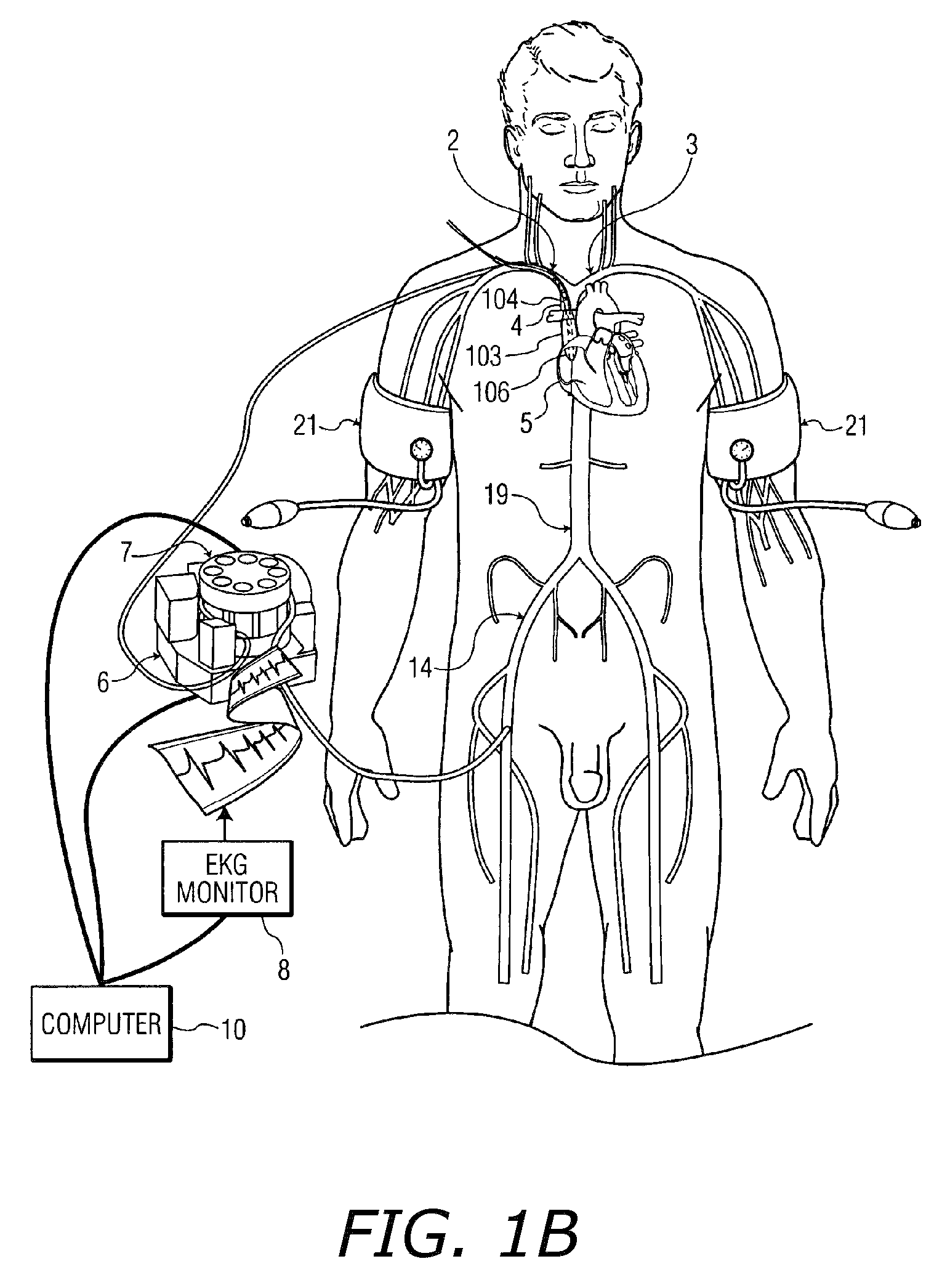
[0084]FIG. 1B shows a zoom view of the thoracic region of FIG. 1A showing in detail the region of insertion of the elongate catheter 104.

[0085]Referring to FIG. 1B, elongate catheter 104 is shown, for proper placement, advanced into the right atrium 5. Upon correct positioning, for example using the guide wire 13, the tip 106 of the elongate catheter 104 is placed at very close proximity to the right atrial-superior vena cava junction 12. The inflatable occlusion balloon 103 is positioned in the superior vena...

second embodiment

IV. Second Embodiment

[0095]With reference now to FIGS. 2A and 2B of the drawings, there is illustrated a method and system, according to another embodiment for selectively perfusing the brain with retrograde cold blood during acute cessation of perfusion to a specific area of the brain due to closure or lack of flow in the arterial blood supply to that segment.

[0096]As illustrated thus far in the previous exemplary embodiment (as shown in FIGS. 1A and 1B), the balloon-tipped catheter 104 includes a single balloon 103. In the present exemplary embodiment (as shown in FIGS. 2A and 2B), an alternative balloon-tipped catheter arrangement is used which includes a pair of balloons 103 and 107. Otherwise, the present embodiment is similar to the previous embodiment in most respects.

[0097]In accordance with the present exemplary embodiment illustrated in FIGS. 2A and 2B, the additional short self-inflation balloon 107 is used to occlude the subclavian vein 2 internally. It is noted that the...

third embodiment

VI. Third Embodiment

Femoral Catheter

[0101]With reference now to FIGS. 4A and 4B of the drawings, there is illustrated a method and system, according to another embodiment, for selectively perfusing the brain with retrograde cold blood during acute cessation of perfusion to a specific area of the brain due to closure or lack of flow in the arterial blood supply to that segment.

[0102]The present embodiment is similar to the previously described embodiments in most respects. However, it is distinguishable from the previously described embodiments in that in the present embodiment, the catheter 104′ is significantly longer than the subclavian catheters 104, 204 previously described which in inserted in the subclavian vein 2. The catheter 104′, also referred to herein as the femoral catheter 104′, is longer than the subclavian catheter 104 to allow for insertion through either right or left femoral vein 15 instead of the right (or left) subclavian vein 2 as described above. The elongated...


PUM


Abstract

A device, system and method for perfusing an oxygenated medium in the cerebral vasculature. In the case of bihemispheric brain perfusion, it includes positioning pressure cuffs on upper extremities; providing a catheter having a multi-region configuration with a balloon; inserting the catheter into a subclavian or femoral vein; advancing the catheter such that the balloon is positioned substantially in the superior vena cava junction substantially proximal to the take-off of the left innominate vein. During a perfusion mode, the cuffs and balloon are inflated causing an increase in cerebral blood flow, retrogradely; and oxygenated blood which may be cooled is pumped from a femoral artery into the catheter for a suitable period. During a non-perfusion mode the cuffs and balloon are deflated. The catheter has at least two regions, namely, guide wire and fluid delivery regions. Optionally, a separate balloon inflation region may be provided. In the case of unilateral (single hemisphere) brain perfusion, it includes providing a catheter having a multi-region configuration with a balloon, inserting the catheter into a subclavian, jugular or femoral vein, advancing the catheter such that the balloon is positioned in the internal jugular vein on the side ipsilateral to the side of the brain requiring perfusion. In this unilateral scenario where the balloon is inflated in the ipsilateral internal jugular vein, no pressure cuffs are needed and only the balloon is inflated and deflated during the perfusion and non-perfusion modes respectively.

Description

RELATED APPLICATIONS[0001]The present invention is a U.S. National Stage application of International Application PCT / US2008 / 063692, International Filing Date 15 May 2008, entitled System, Methods And Apparatus For Cerebral Protection, which claims benefit of U.S. Provisional Application Ser. No. 60 / 938,639, filed May 17, 2007 entitled System, Methods And Apparatus For Cerebral Protection, both of which are incorporated herein by reference.[0002]This application is related to U.S. application Ser. No. 11 / 053,622 filed Feb. 8, 2005 entitled System, Methods and Apparatus for Cerebral Protection, published Sep. 22, 2005 as US 2005 / 0209579, which claims priority from U.S. Provisional Application Ser. No. 60 / 555,221, filed on May 22, 2004 entitled System, Methods And Apparatus For Cerebral Protection, both of which are hereby incorporated by reference.BACKGROUND AND SUMMARY OF THE INVENTION[0003]The present invention relates generally to medical devices and methods including catheters, s...

Claims


Application Information

Patent Timeline
Patent Type & Authority Patents(United States)
IPC IPC(8): A61M31/00A61F2/958A61M5/00
CPCA61M2025/1095A61M25/0029A61M2025/1052A61M2025/1097A61M2025/004A61M25/10A61M2025/0037A61M25/1011A61M1/3613
Inventor YACOUBIAN, VAHE STEPHANSHAHINIAN, HRAYR KARNIG
Owner YACOUBIAN VAHE STEPHAN
Learn More