X-ray CT apparatus and image reconstructing device

a reconstruction device and ct technology, applied in tomography, instruments, applications, etc., can solve the problems of discontinuity of noise characteristics of each tomographic image, and achieve the effect of reducing discontinuity of image quality

Inactive Publication Date: 2010-08-24
GE MEDICAL SYST GLOBAL TECH CO LLC
View PDF22 Cites 0 Cited by
  • Summary
  • Abstract
  • Description
  • Claims
  • Application Information

AI Technical Summary

Benefits of technology

[0005]The present invention has been made in view of the above problem. Various embodiments of the present invention provide an X-ray CT apparatus capable of, when, for example, continuous tomographic images are generated using two different amounts of data as in the case where the above-described X-ray CT imaging in the range not including the heart and the range including the heart is performed, reducing discontinuity of image quality such as noise characteristics between the tomographic images at boundary portions thereof.
[0015]According to an X-ray CT apparatus of the present invention, when, for example, continuous tomographic images are generated using two different amounts of data as in the case where X-ray CT imaging in a range not including the heart and a range including the heart is performed, discontinuity of image quality such as noise characteristics between the tomographic images at boundary portions thereof can be reduced.

Problems solved by technology

As described in the patent document 1, a problem arises in that when upon the chest X-ray CT imaging, the helical scan is performed on the range not including the heart and the range including the heart continuously and image reconstruction is performed in the range not including the heart and the range including the heart using different data amounts (range of view data) in terms of the motion artifact, noise characteristics of each tomographic image become discontinuity at the boundary between the range not including the heart and the range including the range, and when, for example, a chest three-dimensional image is generated using those continuous tomographic images, an artifact occurs in the boundary between the range including the heart and the range not including the heart.

Method used


Image

  • X-ray CT apparatus and image reconstructing device
  • X-ray CT apparatus and image reconstructing device
  • X-ray CT apparatus and image reconstructing device

Examples


Embodiment Construction

[0023]Various embodiments of the present invention will be described in detail in accordance with reference to the accompanying drawings.

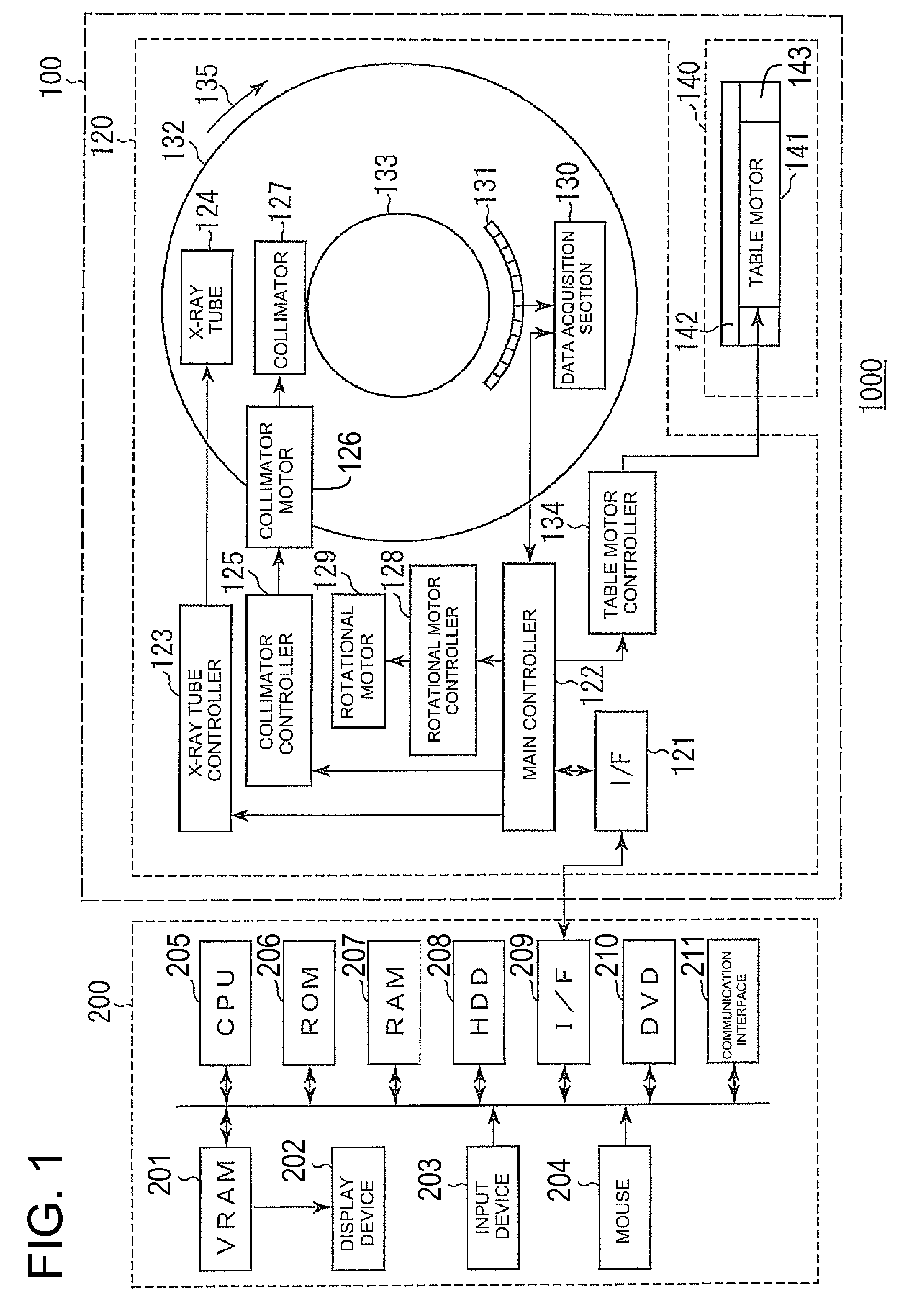
[0024]FIG. 1 is a system configuration diagram of an X-ray CT apparatus 1000 according to one embodiment of the present invention. As shown in FIG. 1, the X-ray CT apparatus 1000 comprises a gantry 120 for detecting the irradiation of a subject (patient) with X rays and the X rays penetrated or transmitted through the subject, an operation console 200 which transmits an instruction signal to the gantry 120 to perform various settings and which reconstructs a tomographic image, based on projection data outputted from the gantry 120 and displays the same, and a conveying device 140 which places the subject thereon and conveys it to the inside of the gantry 120.

[0025]The gantry designated at 120 has the following configuration starting with a main controller (control unit) 122 which conducts its entire control. Reference numeral 121 indicates an inter...


PUM


Abstract

An X-ray CT apparatus includes image reconstructing device which specifies a first imaging range, a second imaging range and a third imaging range located between the first imaging range and the second imaging range in association with each position on a body axis of a subject, image-reconstructs a tomographic image included in the first imaging range using a first projection data amount necessary for image reconstruction of the tomographic image, image-reconstructs a tomographic image included in the second imaging range using a second projection data amount less than the first projection data amount, and image-reconstructs a tomographic image included in the third imaging range using a third projection data amount less than the first projection data amount and greater than the second projection data amount.

Description

CROSS REFERENCE TO RELATED APPLICATIONS[0001]This application claims the benefit of Japanese Patent Application No. 2007-330246 filed Dec. 21, 2007, which is hereby incorporated by reference in its entirety.BACKGROUND OF THE INVENTION[0002]The subject matter disclosed herein relates to an X-ray CT (Computed Tomography) apparatus and an image reconstructing device for imaging a tomographic image of a subject.[0003]As a chest X-ray CT imaging method, there has heretofore been known a method described in, for example, Japanese Unexamined Patent Publication No. 2003-275200. Namely, the patent document has described the method wherein upon chest X-ray CT photography, a continuous helical scan that X-ray projection data are acquired in a range including the heart while a table is being moved at a relatively slow table velocity, and X-ray projection data are acquired in a range not including the heart while the table is being moved at a relatively fast table velocity, is performed thereby ...

Claims


Application Information

Patent Timeline
Patent Type & Authority Patents(United States)
IPC IPC(8): A61B6/00
CPCA61B6/032A61B6/0457A61B6/488G06T11/006G06T2211/412A61B6/027A61B6/0487
Inventor HAGIWARA, AKIRA
Owner GE MEDICAL SYST GLOBAL TECH CO LLC
Why Eureka
Try Eureka