Drain tap

a technology of drain taps and drain pipes, which is applied in the direction of hose connections, washstands, functional valve types, etc., can solve the problems of dripping, wet spots, mold, etc., and achieve the effects of convenient replacement or removal, convenient installation, and compact structur

Inactive Publication Date: 2010-08-31
CAGLE STEPHEN M
View PDF13 Cites 2 Cited by
  • Summary
  • Abstract
  • Description
  • Claims
  • Application Information

AI Technical Summary

Benefits of technology

[0005]The present invention satisfies the need for an inexpensive, compact, conveniently installed article for disposing of water from a condensate hose. Furthermore the present invention provides an article which is easily replaced or removed when appropriate.

Problems solved by technology

Many devices, such as air conditioners or humidifiers, produce unwanted condensate water.
If ignored, such condensate water produces various problems such as dripping, wet spots and mold.
This device, however, is unsatisfactory for several reasons.
First, this prior attempt requires a sealing gasket which necessitates a sealing step in installation.
In addition, the installation requires other elements such as a screw and washer for securing the device necessitating multiple steps in installation.
The bulk of the device is aesthetically undesirable and will interfere with the overall effective drainage area of the drain.
Also, the bulk and profile of the device presents a hazard for those walking in the drain area.
In addition the expense of such an approach is undesirable for such a simple problem.
Finally, the requirement of a gasket creates the possibility of mold, fungal accumulation and the like on the drain.

Method used


Image

  • Drain tap
  • Drain tap
  • Drain tap

Examples


Embodiment Construction

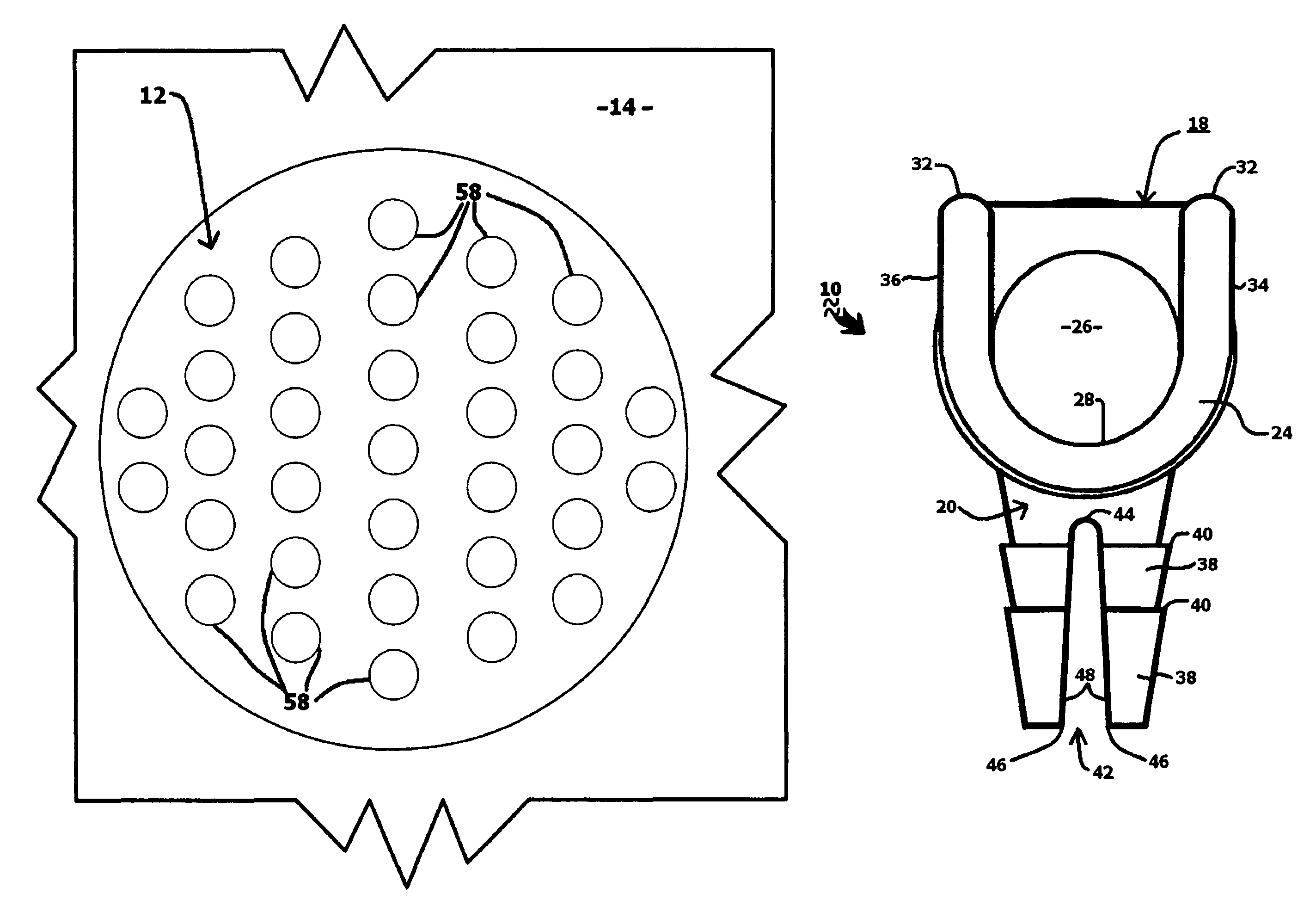
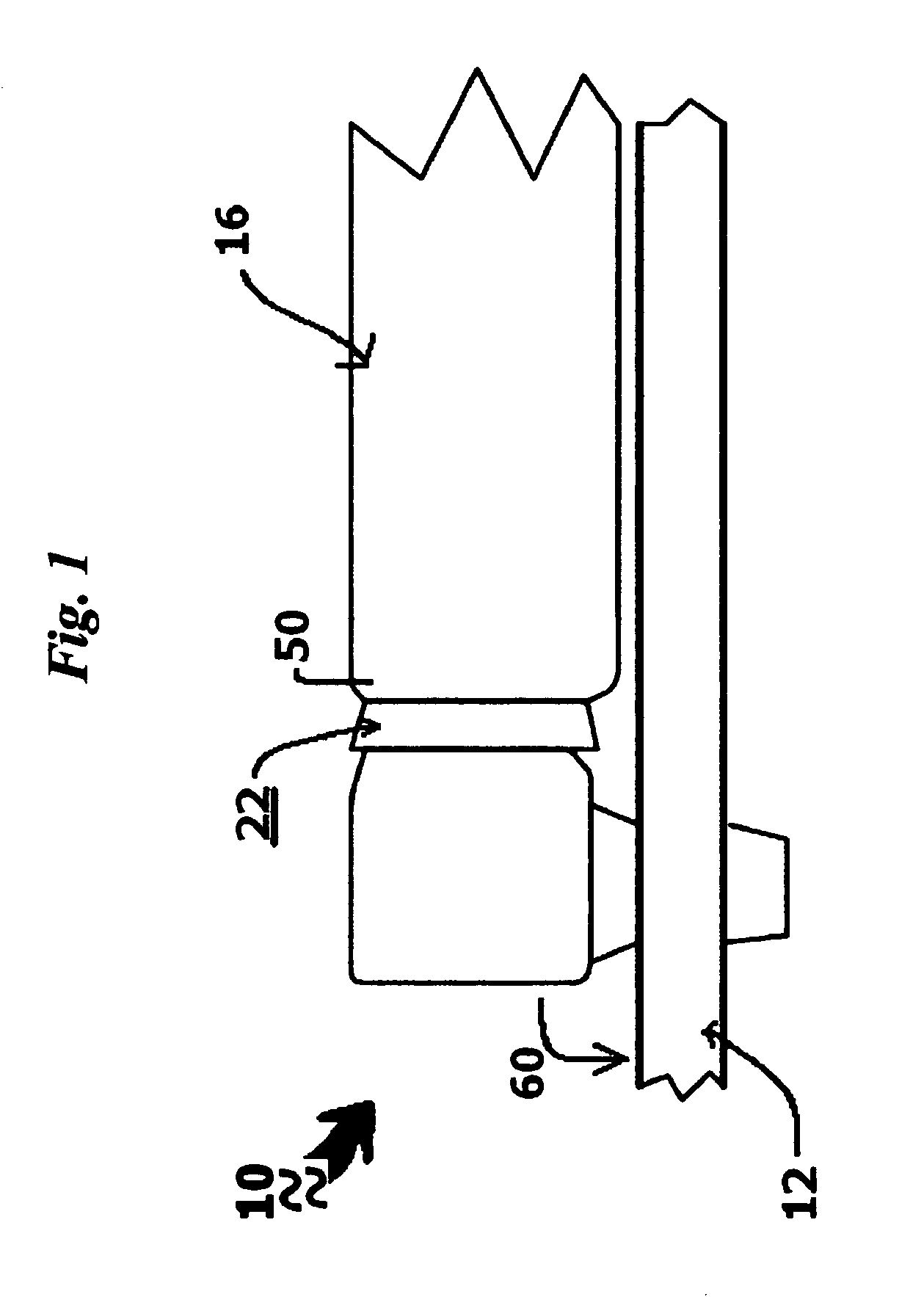
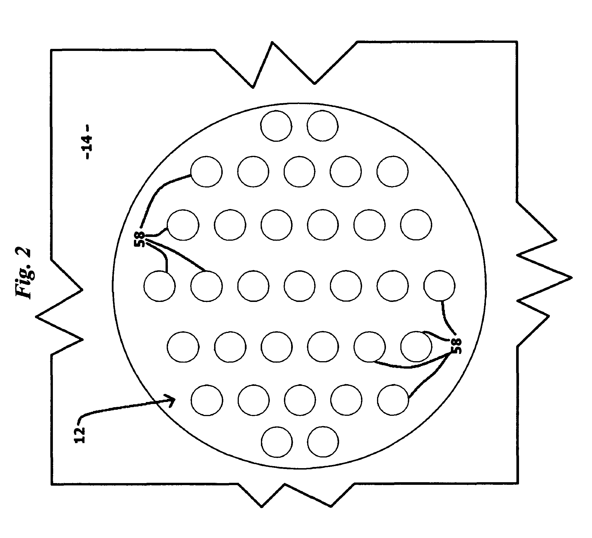
[0015]Referring now to the drawings in general and FIG. 1 in particular, a drain tap 10 according to the present invention, is shown in use with a drain 12 situated on a floor 14 (shown partially in FIG. 2), and a condensate drain hose 16. Drain hose 16 is typically connected to a humidifier or air conditioner (neither of which are shown) or any other device which would generate unwanted moisture or water. Drain tap 10 is substantially made of PVC in the preferred embodiment, but those skilled in the art will readily appreciate that other synthetic resin materials or other suitable materials may also be used.

[0016]Referring to FIG. 3, drain tap 10 is shown to have a base 18, a peg 20 and a hose connector 22. In preferred embodiments the entire length of tap 10 spanning base 18 and hose connector 22 is one and 7 / 16 inch. The lengthwise dimension of peg 20 is ⅝ inch. Other dimensions are readily accommodated by the invention.

[0017]FIG. 4 shows base 18 having a front 24. Base 18 forms ...


PUM


Abstract

An inexpensive, compact, conveniently installed drain tap for disposing of water from a condensate hose. The drain tap channels condensate water from a hose to a drain having at least one drain hole. The tap includes a base forming a hollow channel. The base has a spillway at one end of the channel, in fluid communication therewith. A peg extends downward from the base, including at least one hole barb adapted for retractable insertion into the drain hole. A hose connector is formed on the base, adapted for engagement with one end of the hose. The hose connector is in fluid communication with the base channel, so that when the peg is inserted into the drain hole and one end of the hose is engaged with the hose connector, water may flow through the hose, into the base channel and exit from the spillway onto the drain. In preferred embodiments, the hose connector includes at least one hose barb for gripping engagement of the hose. Additionally, in preferred embodiments the peg includes a U-shaped invagination in the center for compression of the end of the peg when extraction of the peg from the drain hole is desired.

Description

FIELD OF THE INVENTION[0001]This invention relates to drain taps. More particularly, the invention relates to a drain tap for disposal of condensate water to a drain.DESCRIPTION OF RELATED ART[0002]Many devices, such as air conditioners or humidifiers, produce unwanted condensate water. If ignored, such condensate water produces various problems such as dripping, wet spots and mold. The simplest solution is to provide a hose which channels the condensate water to a floor drain. It is desirable to secure the drain end of the hose to a fixed point at the drain to avoid that end moving away from the drain, which could result in a wet spot on the floor or other problems.[0003]The previous attempt at securing the drain end of the hose is illustrated at US 2005 / 0236057 A1. This device, however, is unsatisfactory for several reasons. First, this prior attempt requires a sealing gasket which necessitates a sealing step in installation. In addition, the installation requires other elements s...

Claims


Application Information

Patent Timeline
Patent Type & Authority Patents(United States)
IPC IPC(8): F16L33/00
CPCF16L33/30Y10T137/5835Y10T137/6988
Inventor CAGLE, STEPHEN M.
Owner CAGLE STEPHEN M
Why Eureka
Try Eureka