Methods of driving a scanning beam device to achieve high frame rates

a scanning beam and frame rate technology, applied in the field of methods and scanning beam systems, can solve the problems of large energy storage of scanning elements, affecting the actual scan pattern of illumination spots, and affecting the accuracy of scanning methods, etc., to achieve the effect of improving the frame rate of resonant scanning beam devices, reducing the amount of stored energy, and preventing the scanning of scanning elements in a short amount of tim

Active Publication Date: 2010-08-31
UNIV OF WASHINGTON
View PDF49 Cites 60 Cited by
  • Summary
  • Abstract
  • Description
  • Claims
  • Application Information

AI Technical Summary

Benefits of technology

[0013]The present invention provides methods and systems for improving a frame rate of a resonant scanning beam device. More specifically, the methods and systems of the present invention are directed at rapidly removing the stored energy and stopping the scanning of the scanning element in a short amount of time.
[0016]For improved stability and scan repeatability over various environmental conditions, images of the target area are typically only captured during one portion of the drive signal. For example, in a spiral scan pattern, image data is captured only during a first portion of the scan pattern in which an illumination spot is spiraled outward from an initial, center position. A second portion of the scan pattern is used to return the illumination spot to its initial center position. Once the illumination spot returns to the center position, the drive signal can be repeated.
[0017]In one aspect, the present invention is directed toward generating and applying a drive signal for the second portion of the scan pattern that is configured to return the illumination spot as rapidly as possible from the end of the first portion of the scan pattern to the initial center point. Reducing the retracing time will allow for an increased number of spiral scans that are devoted to image acquisition.

Problems solved by technology

First, because the scanning element is typically driven substantially in resonance, the scanning element tends to store a large amount of energy.
Remapping methods can not correct for the hole in the center of the image.
Unfortunately, the actual scan pattern of the illumination spot may change depending on the environmental factors at the site of its use.
But for the decreasing amplitude portion 19, the changes caused by the temperature may be harder to correct.
If images are captured during both the increasing and decreasing amplitude portions, this may result in a display in which two diverging images are toggled at the frame update rate, which will cause the resultant captured image to become useless.

Method used


Image

  • Methods of driving a scanning beam device to achieve high frame rates
  • Methods of driving a scanning beam device to achieve high frame rates
  • Methods of driving a scanning beam device to achieve high frame rates

Examples


Embodiment Construction

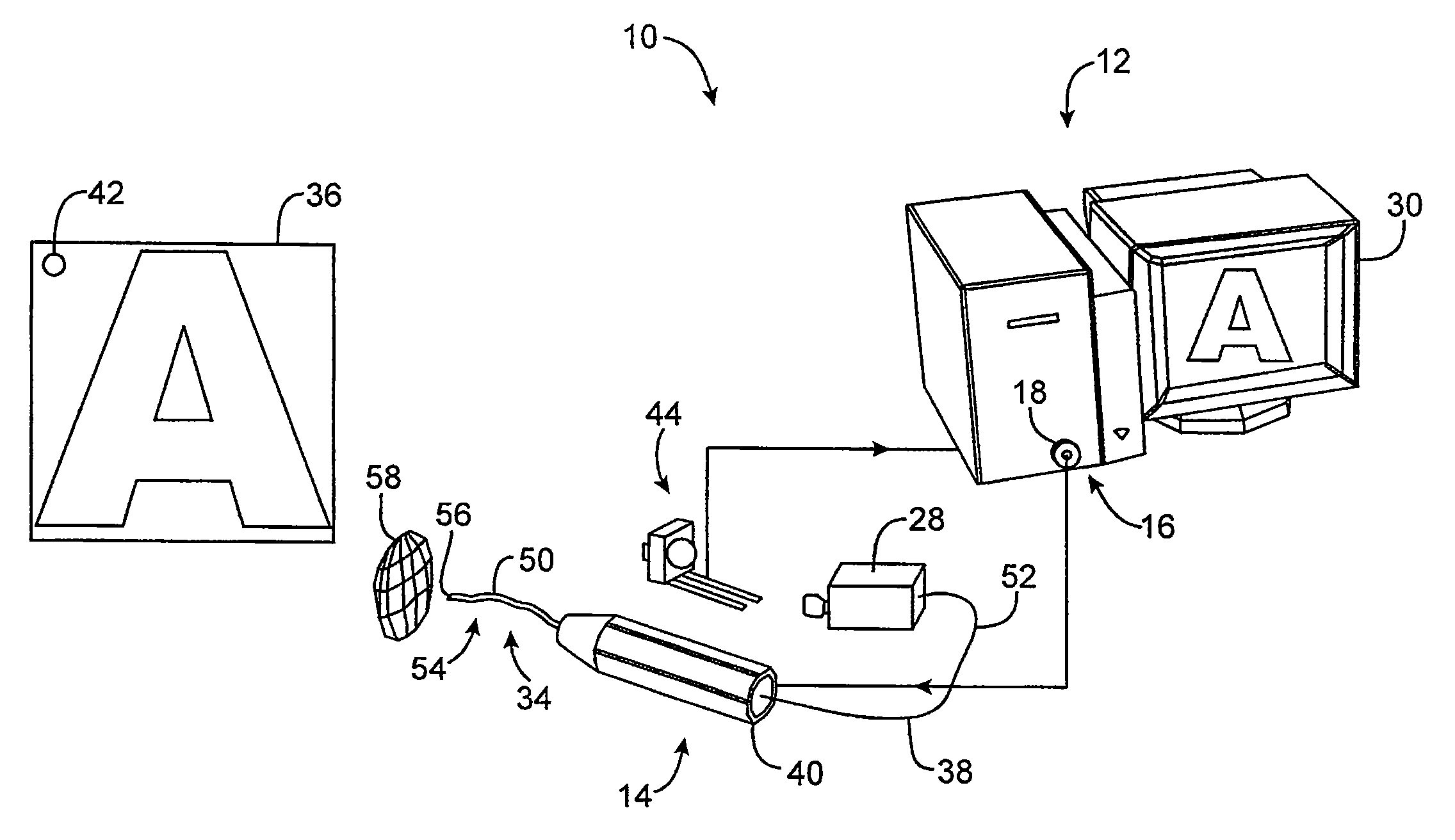
[0035]The present invention provides methods and systems for improving a frame update rate of a scanning beam device by rapidly removing stored energy in a scanning element and returning the scanning element to its starting position.

[0036]The scanning beam systems of the present invention include a scanning beam device and a base station for controlling the image formation or image acquisition of the scanning beam device. The scanning beam devices of the present invention may take on a variety of forms, but are typically in the form of an endoscope, catheter, fiberscope, microscope, boroscope, bar code reader, an image display, or other devices for generating images or acquiring images of a target area. The scanning beam devices of the present invention may be a limited use device (e.g., disposable device) or a multiple-use device. If the device is for medical use, the scanning beam devices will generally be sterile, either being sterilizable or being provided in hermetically sealed...


PUM


Abstract

The present invention provides methods and systems for scanning an illumination spot over a target area. The present invention removes stored energy from a scanning element to stop the scanning element from vibrating and to substantially return the scanning element to its starting position so as to enable high frame rates.

Description

CROSS-REFERENCES TO RELATED APPLICATIONS[0001]The present application is a continuation-in-part of U.S. patent application Ser. No. 11 / 833,831, filed Aug. 3, 2007, which is a continuation of U.S. patent application Ser. No. 11 / 612,888, filed Dec. 19, 2006, which is a continuation of U.S. patent application Ser. No. 11 / 021,981, filed Dec. 23, 2004, the full disclosures of which are incorporated herein by reference.STATEMENT REGARDING FEDERALLY SPONSORED RESEARCH OR DEVELOPMENT[0002]This invention was made with government support under grant number CA094303-R33 awarded by the National Institutes of Health. The government has certain rights in this invention.BACKGROUND OF THE INVENTION[0003]The present invention relates generally to methods and scanning beam systems that provide high frame rates. More particularly, the present invention provides methods and systems for removing energy that is stored in a resonant scanning element.[0004]A scanning beam device that has been developed by ...

Claims


Application Information

Patent Timeline
Patent Type & Authority Patents(United States)
IPC IPC(8): G02B5/00
CPCA61B5/0059G02B26/105G02B26/127H04N3/08
Inventor JOHNSTON, RICHARD SKUNDRAT, MATTHEW JREINHALL, PER G
Owner UNIV OF WASHINGTON
Why Eureka
Try Eureka