Elastomeric track with guide lug reinforcements
a technology of elastomeric track and guide lug, which is applied in the direction of endless track vehicles, vehicles, transportation and packaging, etc., can solve problems such as initiating de-tracking events, and achieve the effects of reducing rotational and/or torsional movements, preventing occurrences of de-tracking, and reducing lateral deformation by wheels
- Summary
- Abstract
- Description
- Claims
- Application Information
AI Technical Summary
Benefits of technology
Problems solved by technology
Method used
Image
Examples
second embodiment
[0046]Alternatively, in a second embodiment shown in FIG. 9, the drive lugs 522 are located in a central row and the guide lugs 525 and 526 are located in two lateral rows on each side of the row of drive lugs 522.
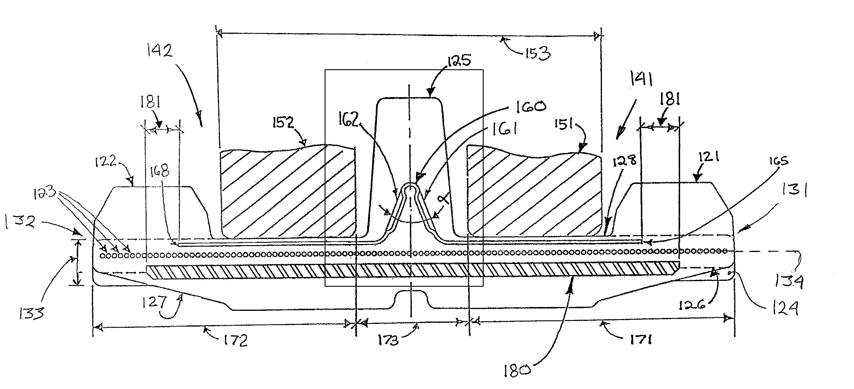
[0047]Referring now to FIGS. 5 and 5C, the outer surface 126 of the track body 124 supports ground-engaging lugs 127 which come in multiple designs to adapt to various types of soil. The ground-engaging lugs 127 are usually disposed over the entire lateral width of the endless elastomeric traction band 120 and along its entire outer circumference. Ground-engaging lugs 127 are usually grouped and each group is generally separated by a laterally extending lugless area, and their alternate sequence provides stability in rotation along the vertical axis (twisting) and the longitudinal axis (torsion) of the traction band 120, therefore minimizing de-tracking occurrences and ensuring a proper vehicle traction on soft terrains.
[0048]The elastomeric traction band 120 is lightweigh...
third embodiment
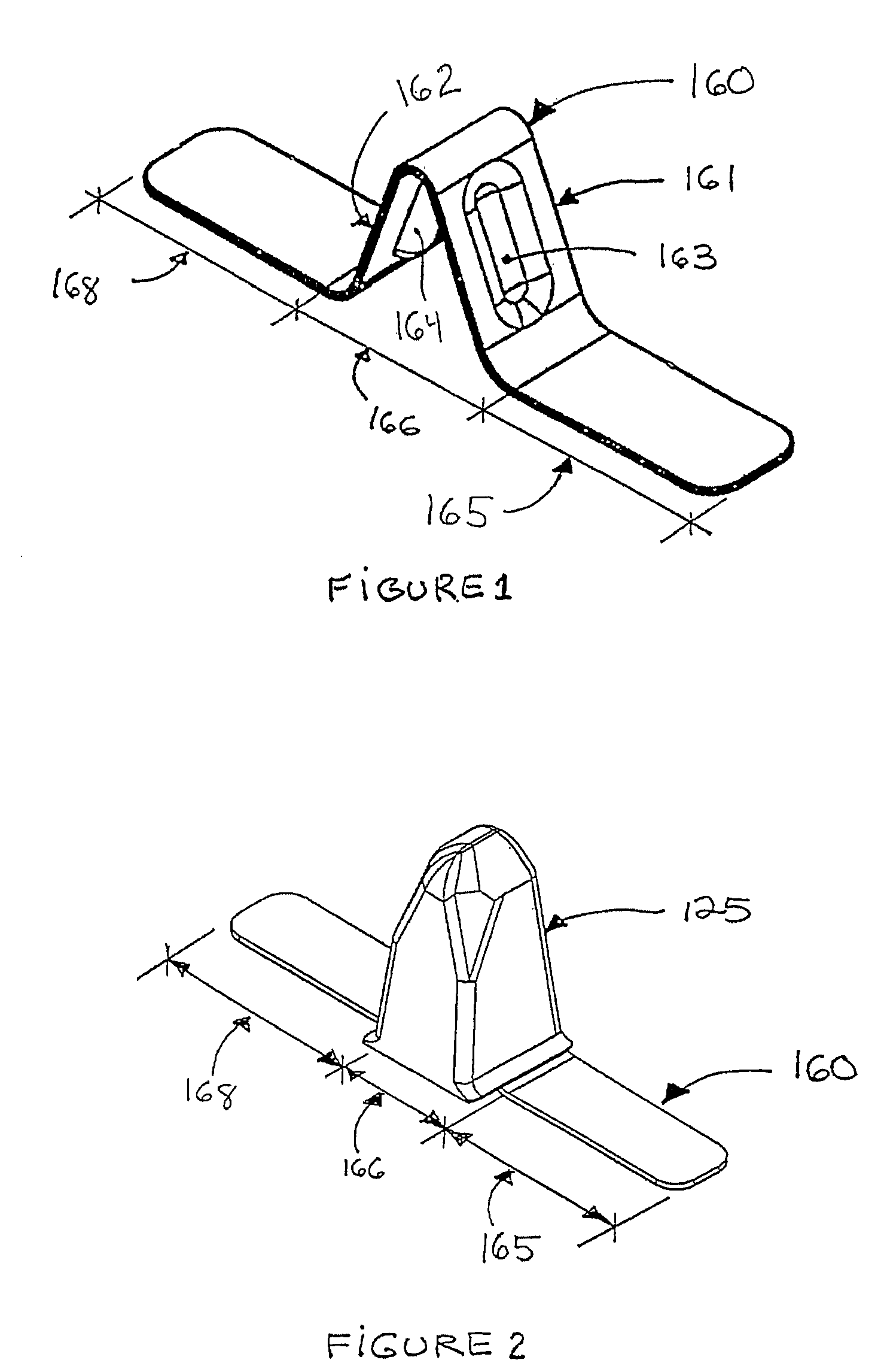
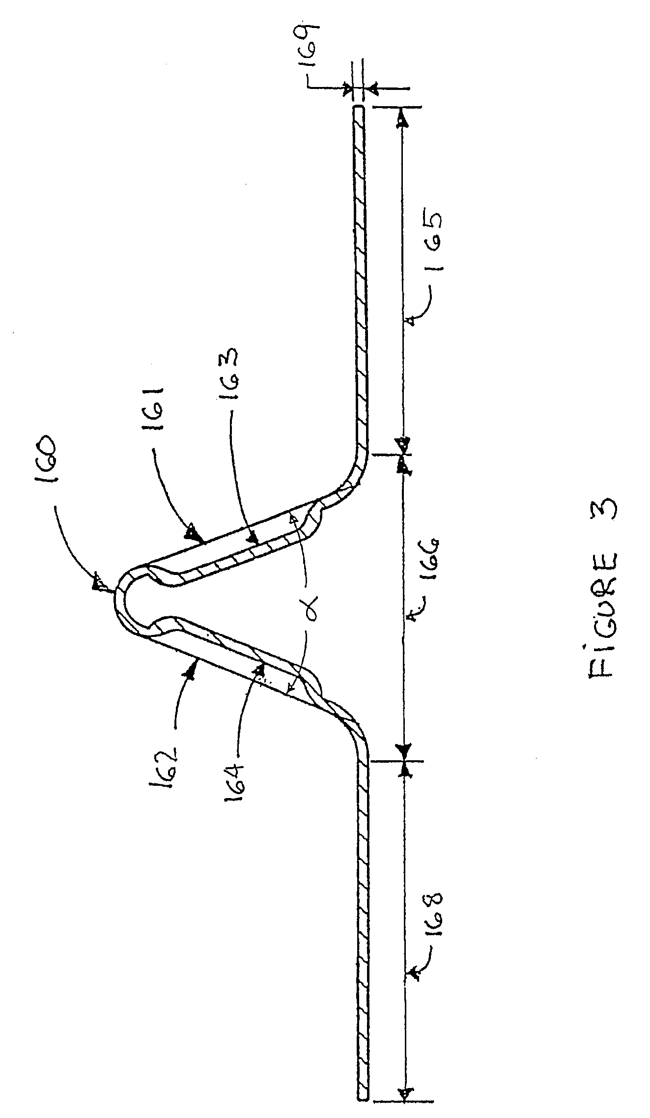
[0060]FIG. 7 illustrates the invention, where each pitch 375 of the traction band 320 comprises a lug reinforcement 360 having a reinforcing portion 366 and two stabilizing portions 365 and 368 on each side of the reinforcing portion 366. The stabilizing portions 358 and 368 are embedded into the band body 324 in a fashion similar to stabilizing portions 165 and 168 of the lug reinforcement 160. Hence, stabilizing portion 365 laterally extends toward and partially underneath drive lugs 321 whereas stabilizing portion 368 laterally extends toward and partially underneath drive lugs 322. The generally inverted V-shaped reinforcing portion 366 is made of two longitudinally extending inclined planar areas 361 and 362 connected together at an angle α. In this embodiment, the inclined planar areas 361 and 362 have a longitudinally variable width in order to occupy, and therefore reinforce, most of the volume of the guide lug 325.
fourth embodiment
[0061]A fourth embodiment is described in FIG. 8. In each pitch 475 of the traction band 420, a guide lug reinforcement 460 is made of a selected number of cords or rods 455. Each cords or rods 455 have a lateral bi-dimensional profile comprising a reinforcing portion 466 and a pair of stabilizing portions 465 and 468 located on each side of the reinforcing portion 466. The generally inverted V-shaped reinforcing portion 466 is mainly located in the guide lug 425 and the longitudinal juxtaposition of each cords or rods 455 defines two inclined planar areas 461 and 462 which are at an angle α (not shown). The stabilizing portions 465 and 468 are embedded in the band body 424, in a fashion similar to stabilizing portions 165 and 168 of the lug reinforcement 160. Hence, stabilizing portion 465 laterally extends toward and partially underneath drive lugs 421 whereas stabilizing portion 468 laterally extends toward and partially underneath drive lugs 422.
[0062]As seen in FIGS. 4 and 5, t...
PUM
 Abstract
Description
Claims
Application Information
 - R&D
- Intellectual Property
- Life Sciences
- Materials
- Tech Scout
- Unparalleled Data Quality
- Higher Quality Content
- 60% Fewer Hallucinations
Browse by: Latest US Patents, China's latest patents, Technical Efficacy Thesaurus, Application Domain, Technology Topic, Popular Technical Reports.
© 2025 PatSnap. All rights reserved.Legal|Privacy policy|Modern Slavery Act Transparency Statement|Sitemap|About US| Contact US: help@patsnap.com


