Compound bow with rigid deflecting stop

Inactive Publication Date: 2015-02-24
OKUPNIAK CHRISTOPH
View PDF35 Cites 2 Cited by
  • Summary
  • Abstract
  • Description
  • Claims
  • Application Information

AI Technical Summary

Benefits of technology

[0028]Furthermore, it is also possible to implement additional components on the shoot-through bow. For example, additional elements can be used to position the compensating cables such that the arrow can be shot through between the compensating cables without obstruction. This is also possible, inter alia, using a cable spreader, of which the U-shaped construction gives rise to an increased spacing between the compensating cables. Furthermore, it is also possible to fit one or mor

Problems solved by technology

Even just a slight action or movement can result in a sudden release of drawing tension from a bow drawn in such a way.
Particularly in those cases where there is no arrow placed in position, which could convert the stored energy into kinetic energy, the above described sudden release of drawing tension from the bow may result in parts of the bow, in particular the string, the limbs or even

Method used


Image

  • Compound bow with rigid deflecting stop
  • Compound bow with rigid deflecting stop
  • Compound bow with rigid deflecting stop

Examples


Embodiment Construction

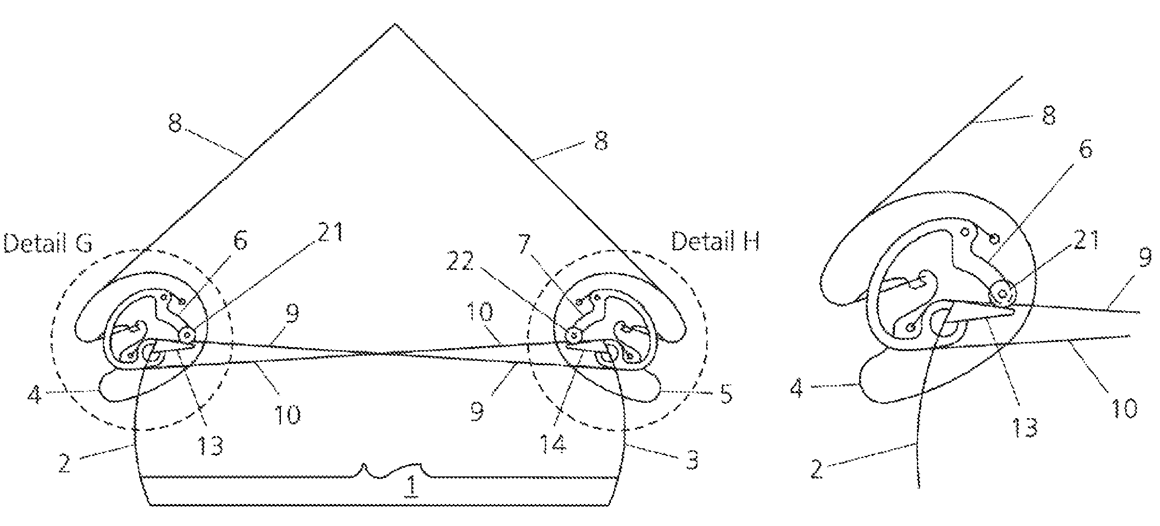
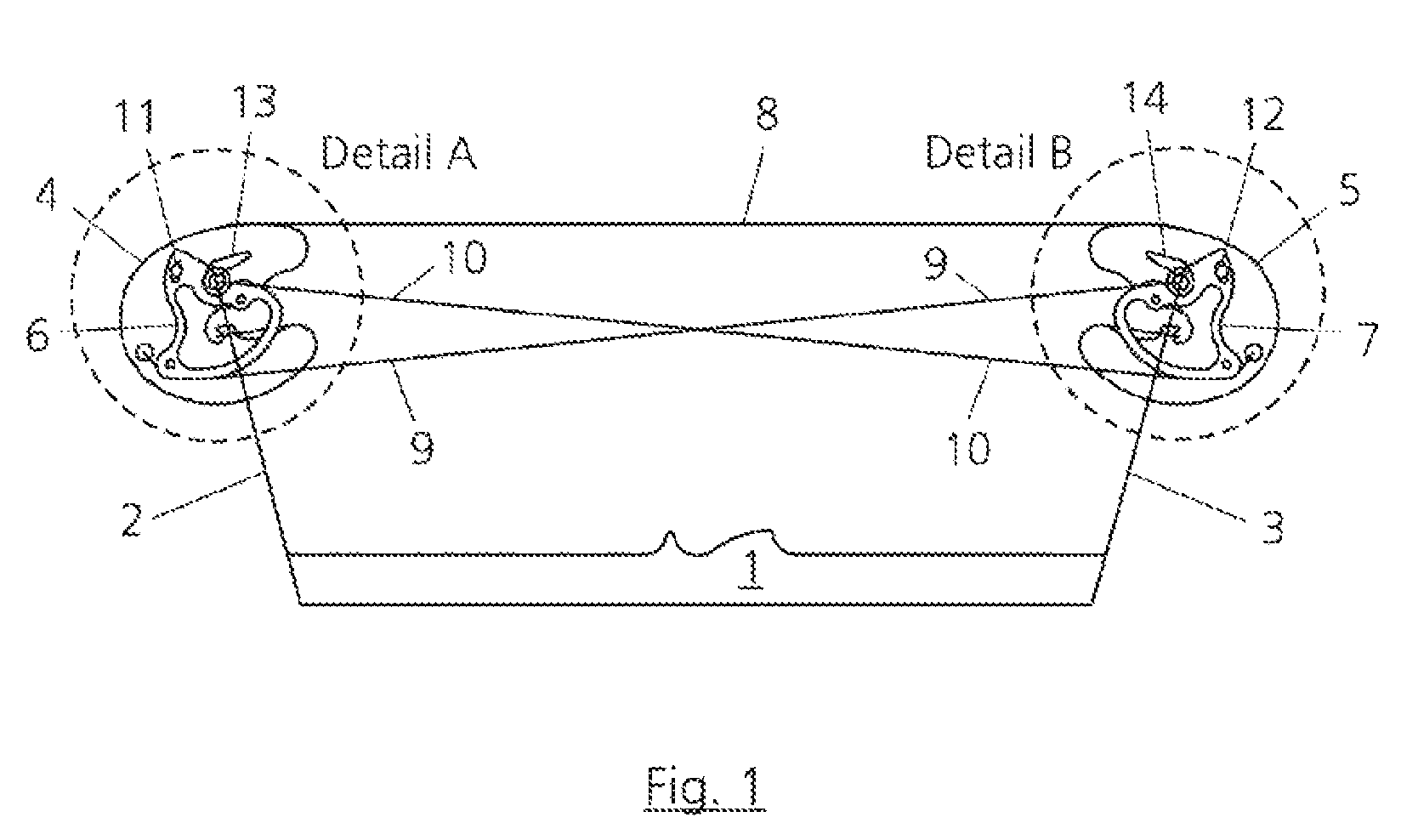
[0046]FIG. 1 shows a schematic illustration of an exemplary embodiment of an undrawn type 1 bow according to the invention having the centrepiece 1 followed by the two limbs 2 and 3. The string pulleys 4 and 5 are arranged in a rotatable manner at each of the ends of the limbs 2 and 3. In each case two cable pulleys are connected rigidly to the string pulleys 4 and 5, wherein the cable pulleys which can be seen in FIG. 1 are designated by 6 and 7. The string 8 here runs in a first groove on the string pulleys 4 and 5, whereas the compensating cables9 and 10 run in a second groove and third groove, respectively, on the cable pulleys 6 and 7. In addition, in each case one deflecting stop 11 and 12 is mounted on the rigidly interconnected string and cable pulleys 6 and 7. The deflecting stop 11 or 12 here serves to limit the drawing movement of the bow. The stop elements 13 and 14 may also be fitted on the limbs (cf. FIG. 7).

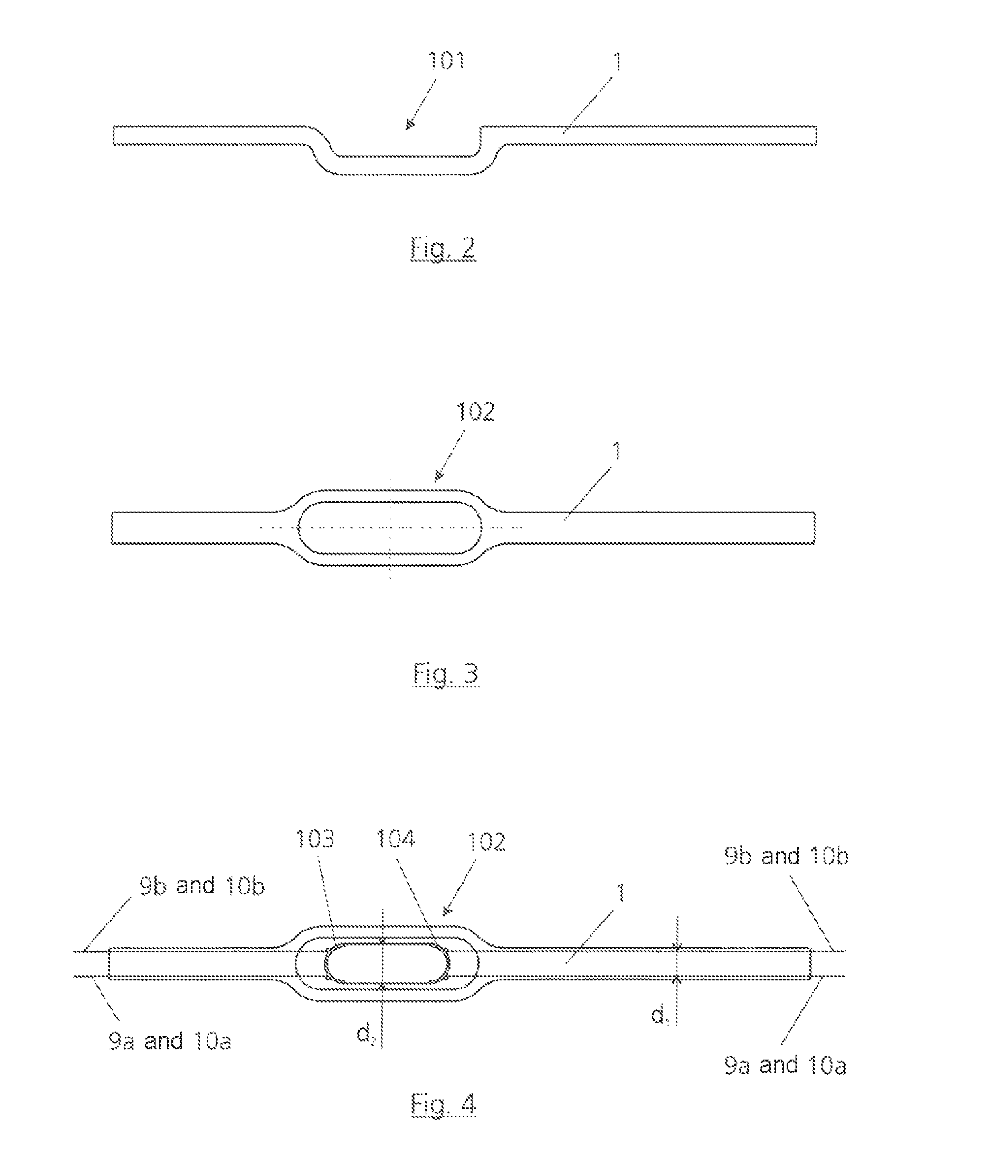
[0047]FIG. 2 contains a centrepiece 1 of a shoot-through bow ...


PUM


Abstract

Bow having a centerpiece, two flexurally elastic limbs, a string, at least one string pulley, mounted in one end of a limb and intended for accommodating the string, and at least two cable pulleys, connected rigidly to the string pulley and intended for accommodating and guiding compensating cables, and in each case at least one cable pulley is arranged on both sides of the string pulley, and the subassembly made up of the string pulley and cable pulleys is mounted in a rotatable manner in each case, and at least one deflecting stop is present for the purpose of limiting the deflection of the string, and this deflecting stop, when the string is deflected, strikes against a limb or against a stop element connected rigidly to the limb.

Description

[0001]This application claims the benefit of German Application No. DE 10 2011 004 036.6 filed Feb. 14, 2011 and entitled COMPOUND BOW WITH RIGID DEFLECTING STOP, which is hereby incorporated herein by reference in its entirety.BACKGROUND[0002]1. Field of the Invention[0003]The invention relates to a bow, for example a sports or hunting bow or a crossbow.[0004]2. Description of the Related Art[0005]The principle common to the aforementioned pieces of sports or hunting equipment is that an archer draws a string by means of one or more elastic elements, so-called limbs, and then lets it go. The string here accelerates an arrow in the direction of a target. Modern bows or crossbows have little in common with the examples which are known from history. In particular, the variation in force when the string is drawn has, in the meantime, been adjusted optimally to the envisaged use. Therefore for example the force which has to be applied in order to draw a hunting bow in the first instance...

Claims


Application Information

Patent Timeline
IPC IPC(8): F41B5/10F41B5/14
CPCF41B5/10F41B5/14F41B5/105Y10S124/90
Inventor OKUPNIAK, CHRISTOPH
Owner OKUPNIAK CHRISTOPH
Why Eureka
Try Eureka