Elastomeric Track with Guide Lug Reinforcements

a technology of elastomeric track and guide lug, which is applied in the direction of endless track vehicles, vehicles, transportation and packaging, etc., can solve problems such as initiating de-tracking events, and achieve the effects of reducing rotational and/or torsional movements, preventing occurrences of de-tracking, and reducing lateral deformation by wheels

Active Publication Date: 2008-05-01
SOUCY INT
View PDF22 Cites 36 Cited by
  • Summary
  • Abstract
  • Description
  • Claims
  • Application Information

AI Technical Summary

Benefits of technology

[0019] In one embodiment, this invention introduces guide lug reinforcements to the endless traction band made from elastomeric materials, in the form of sheet-like plates, cords, rods or fabric destined to be inserted and integrally molded at a selected interval into the traction band. The guide lug reinforcements are disposed in such numbers, as required, to enhance the lateral rigidity and the resiliency of the guide lugs with respect to de-tracking occurrences.
[0024] The guide lug reinforcements help to laterally stabilize the wheels / traction band assembly as the traction band rotates. The guide lugs lateral deformation by the wheels is reduced and preferably prevented by the guide lug reinforcements which provide a rigid yet resilient lateral support. The reinforcements, with their vertically inclined planar areas, first absorb the lateral forces and then redirect the misaligned track toward its usual operating position.
[0025] In accordance with the present invention, since the guide lug reinforcements are physically distinct from the stiffening elements embedded into the body of the track, the lateral deformation of the guide lug reinforcements is not directly transmitted to the stiffening elements as in the prior art. Indeed, by providing one or more intermediate layers of elastomeric material between the guide lug reinforcements and the stiffening elements, these layers of elastomeric materials can further absorb a portion of the lateral or shear forces applied to the guide lugs, reducing rotational and / or torsional movements of the whole track and further preventing occurrences of de-tracking.
[0026] Furthermore, since the guide lug reinforcements and the stiffening elements are physically distinct, each of which can be optimally located in the track body according to their respective purposes. Hence, the stabilizing portions of the guide lug reinforcements can be embedded into the body of the track between the neutral axis and the inner surface whereas the stiffening elements can be embedded into the body of the track between the neutral axis and the outer surface. Notably, by locating the stiffening elements between the neutral axis and the outer surface and by providing essentially flat stabilizing portions, it becomes possible to reduce the thickness of the portion of the body of the track between the neutral axis and the inner surface.

Problems solved by technology

The wear and the use of the traction band under extreme conditions, like high lateral loads, sometimes initiates de-tracking events which are usually generated by a combined action of friction and interference between the wheels and the guide lugs.

Method used


Image

  • Elastomeric Track with Guide Lug Reinforcements
  • Elastomeric Track with Guide Lug Reinforcements
  • Elastomeric Track with Guide Lug Reinforcements

Examples


second embodiment

[0045] Alternatively, in a second embodiment shown in FIG. 9, the drive lugs 522 are located in a central row and the guide lugs 525 and 526 are located in two lateral rows on each side of the row of drive lugs 522.

[0046] Referring now to FIGS. 5 and 5A, the outer surface 126 of the track body 124 supports ground-engaging lugs 127 which come in multiple designs to adapt to various types of soil. The ground-engaging lugs 127 are usually disposed over the entire lateral width of the endless elastomeric traction band 120 and along its entire outer circumference. Ground-engaging lugs 127 are usually grouped and each group is generally separated by a laterally extending lugless area, and their alternate sequence provides stability in rotation along the vertical axis (twisting) and the longitudinal axis (torsion) of the traction band 120, therefore minimizing de-tracking occurrences and ensuring a proper vehicle traction on soft terrains.

[0047] The elastomeric traction band 120 is lightw...

third embodiment

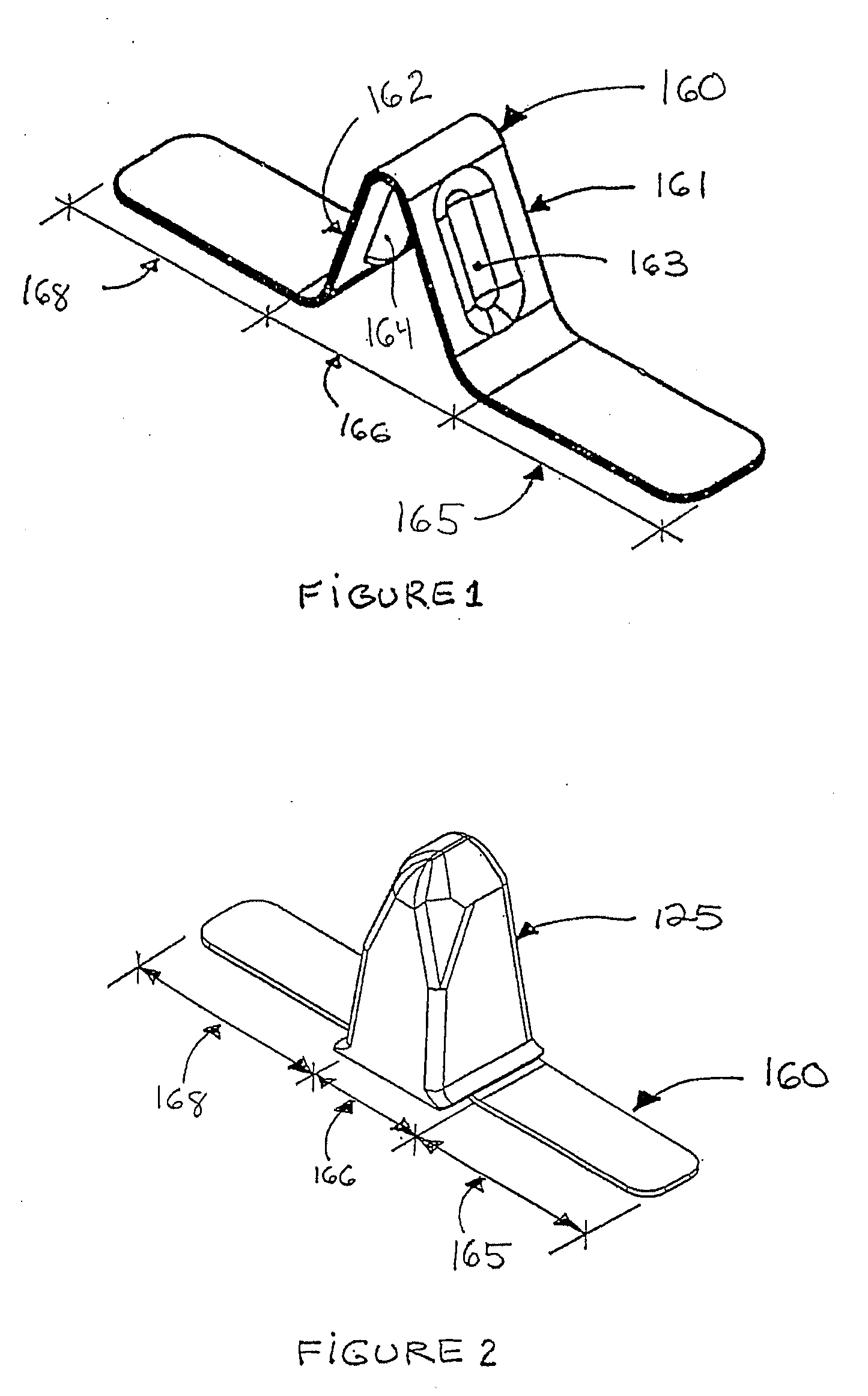
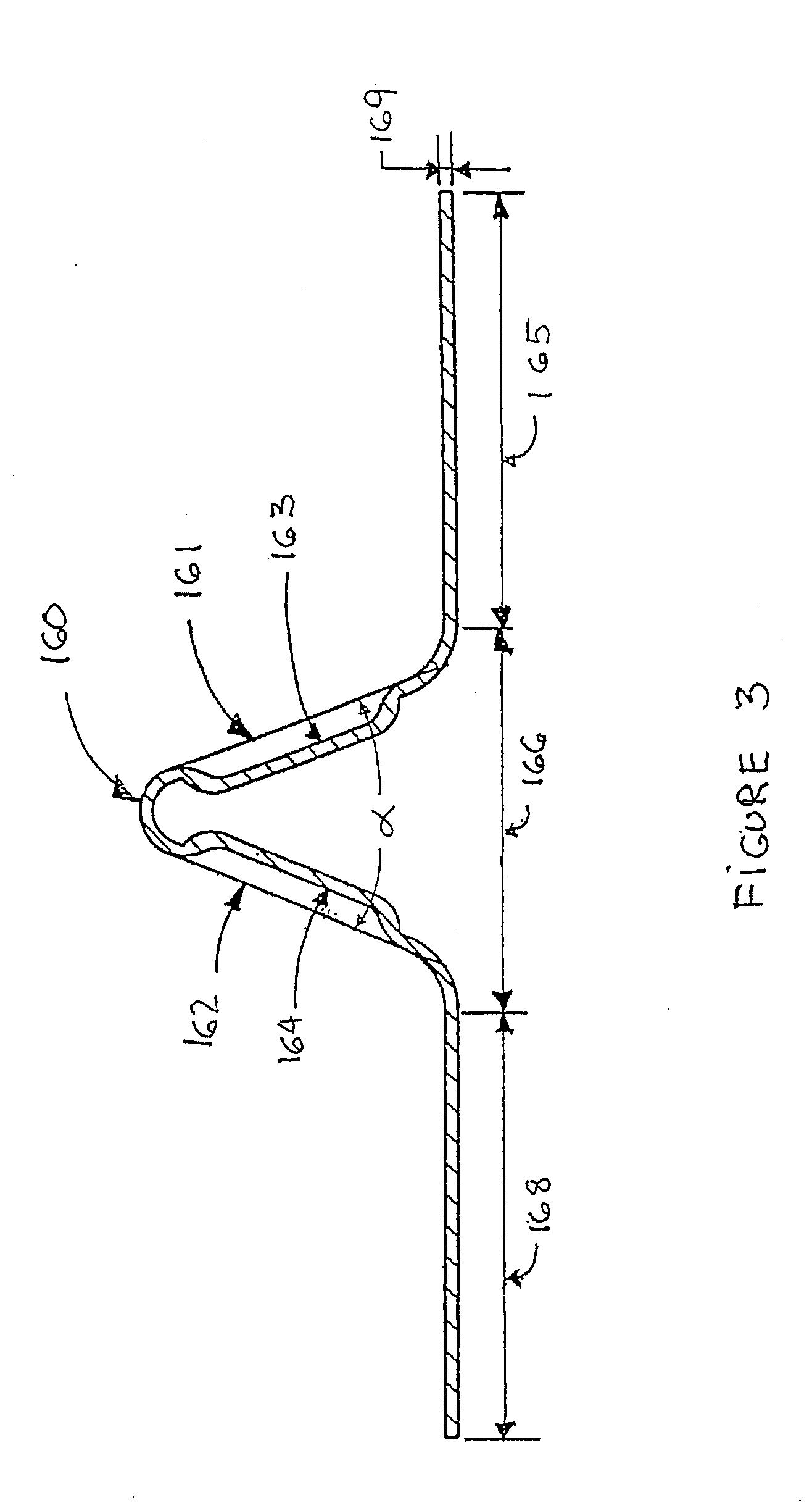
[0059]FIG. 7 illustrates the invention, where each pitch 375 of the traction band 320 comprises a lug reinforcement 360 having a reinforcing portion 366 and two stabilizing portions 365 and 368 on each side of the reinforcing portion 366. The stabilizing portions 358 and 368 are embedded into the band body 324 in a fashion similar to stabilizing portions 165 and 168 of the lug reinforcement 160. Hence, stabilizing portion 365 laterally extends toward and partially underneath drive lugs 321 whereas stabilizing portion 368 laterally extends toward and partially underneath drive lugs 322. The generally Λ-shaped reinforcing portion 366 is made of two longitudinally extending inclined planar areas 361 and 362 connected together at an angle α. In this embodiment, the inclined planar areas 361 and 362 have a longitudinally variable width in order to occupy, and therefore reinforce, most of the volume of the guide lug 325.

fourth embodiment

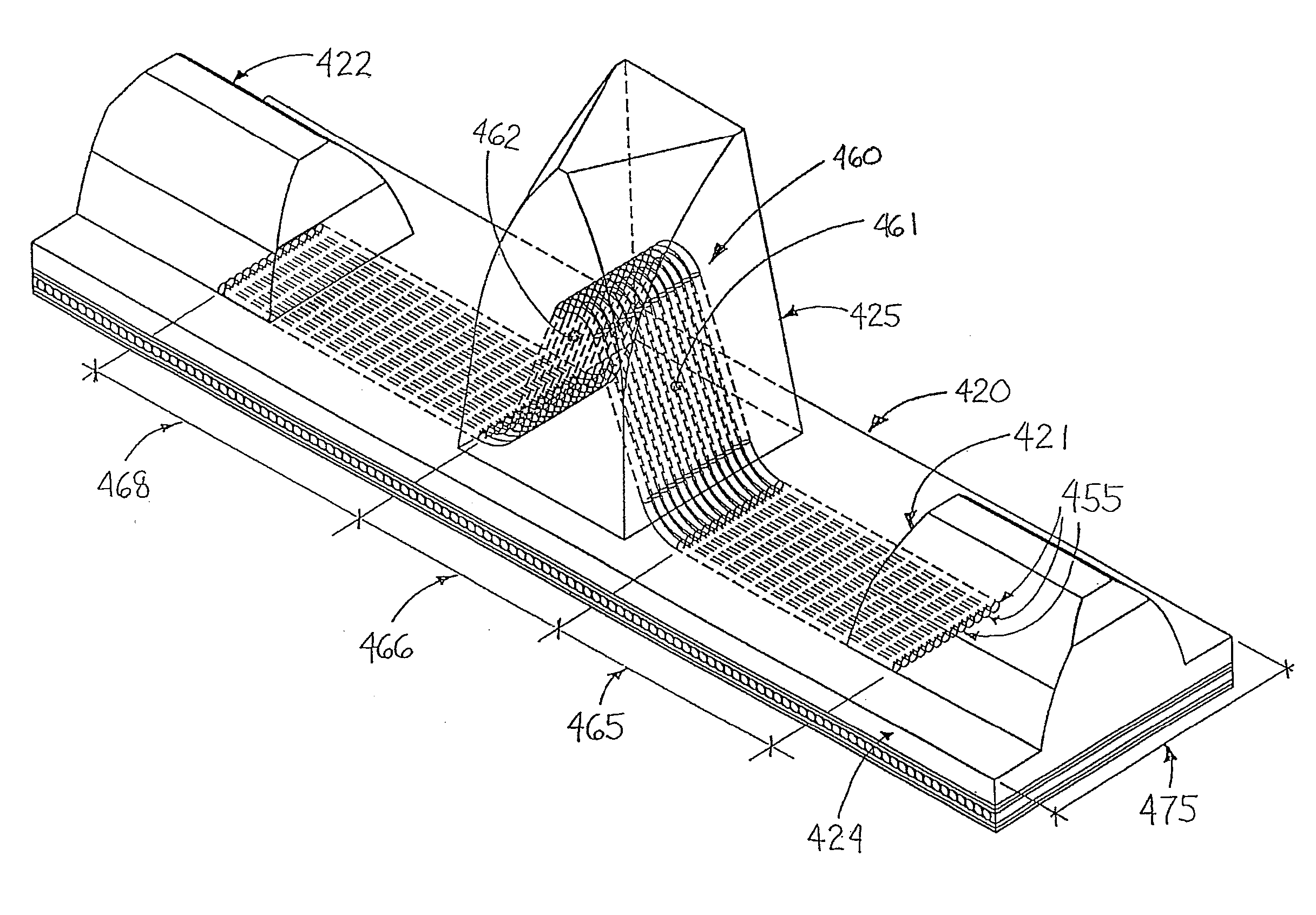
[0060] A fourth embodiment is described in FIG. 8. In each pitch 475 of the traction band 420, a guide lug reinforcement 460 is made of a selected number of cords or rods 455. Each cords or rods 455 have a lateral bi-dimensional profile comprising a reinforcing portion 466 and a pair of stabilizing portions 465 and 468 located on each side of the reinforcing portion 466. The generally Λ-shaped reinforcing portion 466 is mainly located in the guide lug 425 and the longitudinal juxtaposition of each cords or rods 455 defines two inclined planar areas 461 and 462 which are at an angle α (not shown). The stabilizing portions 465 and 468 are embedded in the band body 424, in a fashion similar to stabilizing portions 165 and 168 of the lug reinforcement 160. Hence, stabilizing portion 465 laterally extends toward and partially underneath drive lugs 421 whereas stabilizing portion 468 laterally extends toward and partially underneath drive lugs 422.

[0061] As seen in FIGS. 4 and 5, the use ...


PUM


Abstract

This invention relates to an endless elastomeric traction band that is used to propel tracked vehicles. The traction band generally comprises a main body defining an outer ground-engaging surface and an inner wheel-engaging surface. The outer surface is generally provided with ground-engaging traction lugs. The inner surface of the traction band is preferably provided with one or more row of longitudinally aligned guide lugs and one or more rows of longitudinally aligned drive lugs. Additionally, guide lug reinforcements are inserted into said guide lugs and said band body to laterally reinforce the guide lugs and minimize de-tracking occurrences.

Description

CROSS-REFERENCE TO RELATED APPLICATIONS [0001] The present patent application is a continuation-in-part of commonly assigned U.S. patent application Ser. No. 10 / 791,571, and claims the benefits of priority thereof. The disclosure of U.S. patent application Ser. No. 10 / 791,571 is incorporated herein by reference.FIELD OF THE INVENTION [0002] The present invention generally relates to tracked vehicles which use elastomeric tracks for propulsion. More particularly, the present invention relates to the elastomeric tracks used on such tracked vehicles. Without being limitative in nature, the present invention particularly relates to elastomeric tracks for use on heavy tracked vehicles (i.e. vehicles weighing 5000 kg or more) such as military vehicles (e.g. tanks and transport vehicles) and heavy machinery (e.g. excavators, bulldozers and forestry equipments). BACKGROUND OF THE INVENTION [0003] Numerous types of vehicles are frequently used on terrain where it is difficult for pneumatic t...

Claims


Application Information

Patent Timeline
Patent Type & Authority Applications(United States)
IPC IPC(8): B62D55/24
CPCB62D55/244
Inventor SOUCY, GILLESDELISLE, MARCDELAND, ANDRE
Owner SOUCY INT
Why Eureka
Try Eureka