Vehicle lamp

a technology for vehicles and lamps, applied in fixed installations, lighting and heating apparatus, lighting support devices, etc., can solve the problems of reducing the efficiency of utilizing light sources by a certain amount, and achieve the effect of compact formation of lamps and increasing the efficiency of utilizing light flux

Inactive Publication Date: 2010-08-31
KOITO MFG CO LTD
View PDF9 Cites 3 Cited by
  • Summary
  • Abstract
  • Description
  • Claims
  • Application Information

AI Technical Summary

Benefits of technology

[0009]One or more embodiments of the invention provide a vehicle lamp constituting a light source by a light emitting element capable of increasing an efficiency of utilizing a light flux of a light source even though compact formation of the lamp is achieved.
[0010]In accordance with one or more embodiments of the invention, an efficiency of utilizing a light flux is increased by an arrangement of a light emitting element and a predetermined reflector.

Problems solved by technology

However, such light is not controlled to deflect by the lens and therefore, the light cannot be effectively utilized as front illuminating light and therefore, there poses a problem that an efficiency of utilizing a light flux of a light source is reduced by that amount.

Method used


Image

  • Vehicle lamp
  • Vehicle lamp
  • Vehicle lamp

Examples


Embodiment Construction

[0047]Exemplary embodiments of the invention will be explained in reference to the drawings as follows.

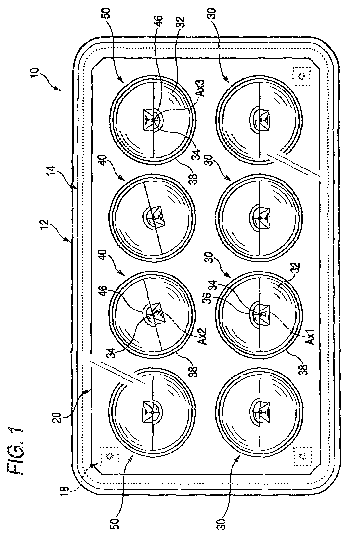
[0048]FIG. 1 is a front view showing a vehicle headlamp 10 according to an exemplary embodiment of the invention.

[0049]As shown by the drawing, the vehicle headlamp 10 according to the exemplary embodiment is structured by a constitution in which eight lamp units 30, 40, 50 are contained at inside of a lamp chamber formed by a lamp body 12 and a transparent cover 14 in a transparent state attached to an opening portion of a front end of the lamp body 12 as a vehicle lamp.

[0050]The eight lamp units 30, 40, 50 are fixedly supported by a common metal made bracket 20 by upper and lower two stages arrangement. The metal made bracket 20 is formed by a shape of a vertical panel and is supported by the lamp body 12 inclinably in an up and down direction and a left and right direction by way of an aiming mechanism 18.

[0051]Among the eight lamp units 30, 40, 50, four of the lamp units 30 arr...


PUM


Abstract

A lamp unit as a vehicle lamp is structured by a compact constitution including a lens arranged on an optical axis extending in a front and rear direction of the lamp, and a light emitting element arranged rearward from the lens. The light emitting element is arranged at a vicinity of the rear side focal point in a state of inclining a light emitting chip in a skewed upper direction relative to a direction of a front face of the lamp. A vicinity of the light emitting element is arranged with a reflector for reflecting light from the light emitting chip to the lens. Light directed in a direction proximate to the optical axis emitted from the light emitting chip is incident on the lens, and also most of other light is made to be incident on the lens by being reflected by the reflector.

Description

[0001]This application claims foreign priority from Japanese Patent Application Nos. 2006-012705 filed on Jan. 20, 2006, and 2006-331191 filed on Dec. 7, 2006, the entire contents of which are hereby incorporated by reference.BACKGROUND OF THE INVENTION[0002]1. Field of the Invention[0003]The present invention relates to a vehicle lamp constituting a light source by a light emitting element.[0004]2. Related Art[0005]In recent years, a light emitting element of a light emitting diode or the like has been frequently used.[0006]For example, JP-A-2005-044683 describes a vehicle lamp including a lens arranged on an optical axis extending in a front and rear direction of a lamp, and a light emitting element arranged on a rear side of the lens, and constituted such that directly emitted light from the light emitting element is controlled to deflect by the lens to be illuminated to a front side of the lamp. Further, compact formation of the lamp can be achieved by adopting such a vehicle la...

Claims


Application Information

Patent Timeline
Patent Type & Authority Patents(United States)
IPC IPC(8): B60Q1/00F21V11/00F21V21/00F21S8/12F21V13/00F21W101/10F21W107/00F21Y101/02
CPCF21S48/1159F21S48/1163F21S48/1258F21S48/145F21Y2101/02F21Y2115/10F21S41/148F21S41/153F21S41/155F21S41/255F21S41/43
Inventor ISHIDA, HIROYUKI
Owner KOITO MFG CO LTD
Why Eureka
Try Eureka