
Multi-input multi-output system and method for demodulating a transmitting vector in a receiver of the system

a multi-output system and transmitting vector technology, applied in multi-frequency code systems, power management, wireless communication, etc., can solve problems such as complex and thus difficult to achieve, deterioration of performance, and inability to achieve maximum diversity, so as to achieve the effect of easy detection of transmitting vectors

Inactive Publication Date: 2010-08-31
ELECTRONICS & TELECOMM RES INST
View PDF19 Cites 7 Cited by
  • Summary
  • Abstract
  • Description
  • Claims
  • Application Information

AI Technical Summary

Benefits of technology

The present invention is about a system and method for detecting and demodulating a transmitting vector in a multi-input multi-output system. The invention allows for easy detection of a transmitting vector that is assigned different modulation and power coefficients to each antenna. The technical effects of the invention include improved signal detection and more efficient demodulation of the transmitting vector.

Problems solved by technology

This system, however, is complex and thus difficult to implement.
This system simplifies a conventional D-BLAST system by means of hardware implementation, but cannot accomplish maximum diversity and thus has deteriorated performance.
However, in such a conventional V-BLAST system, since all transmitting antennas use the same modulation system and power, high performance is achieved at the cost of a receiver having a complex structure.

Method used


Image

  • Multi-input multi-output system and method for demodulating a transmitting vector in a receiver of the system
  • Multi-input multi-output system and method for demodulating a transmitting vector in a receiver of the system
  • Multi-input multi-output system and method for demodulating a transmitting vector in a receiver of the system

Examples


Embodiment Construction

[0029]Hereinafter, exemplary embodiments of the present invention will be described in detail. However, the present invention is not limited to the embodiments disclosed below, but can be implemented in various forms. Therefore, the following embodiments are described in order for this disclosure to be complete and enabling to those of ordinary skill in the art.

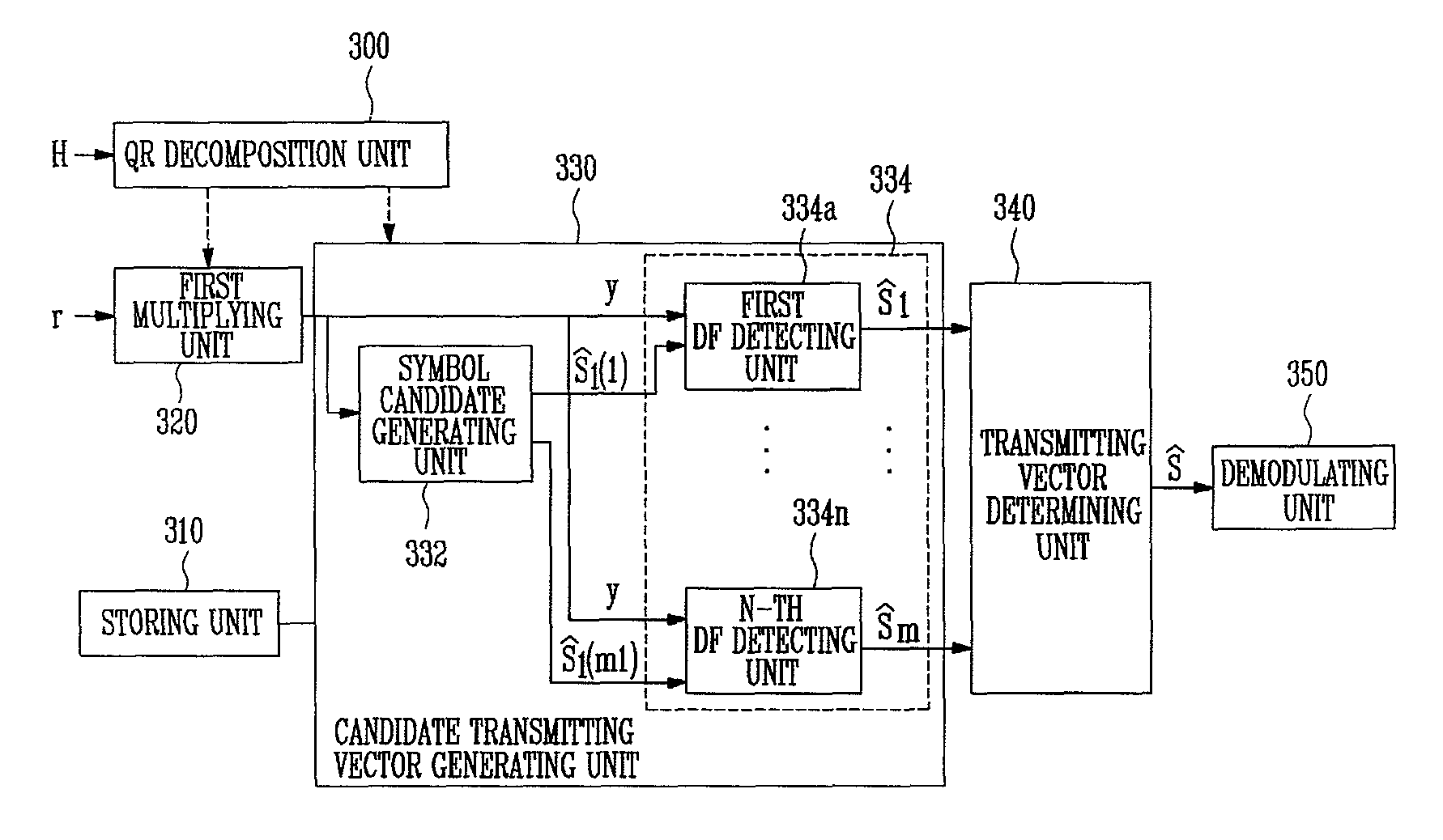
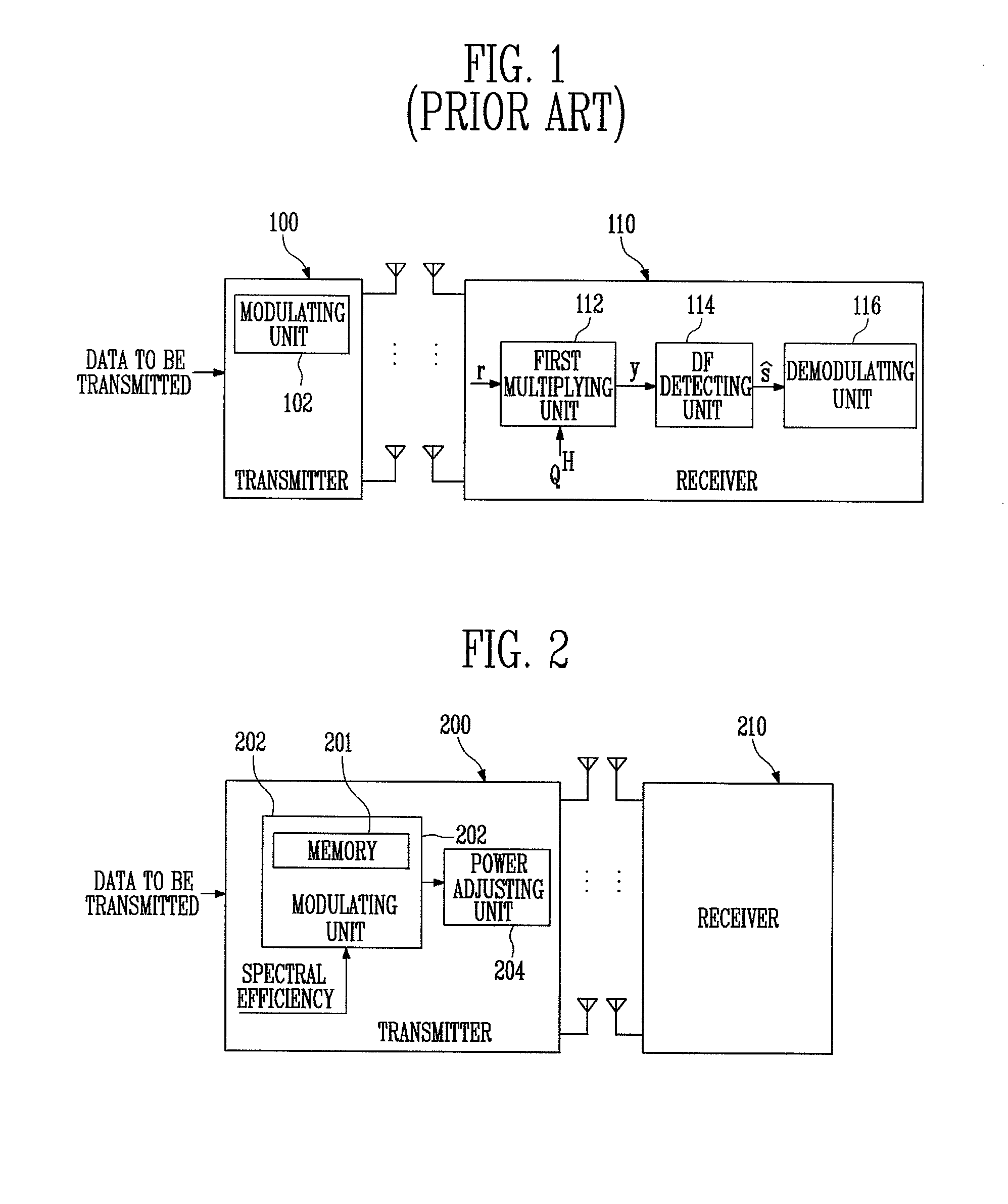
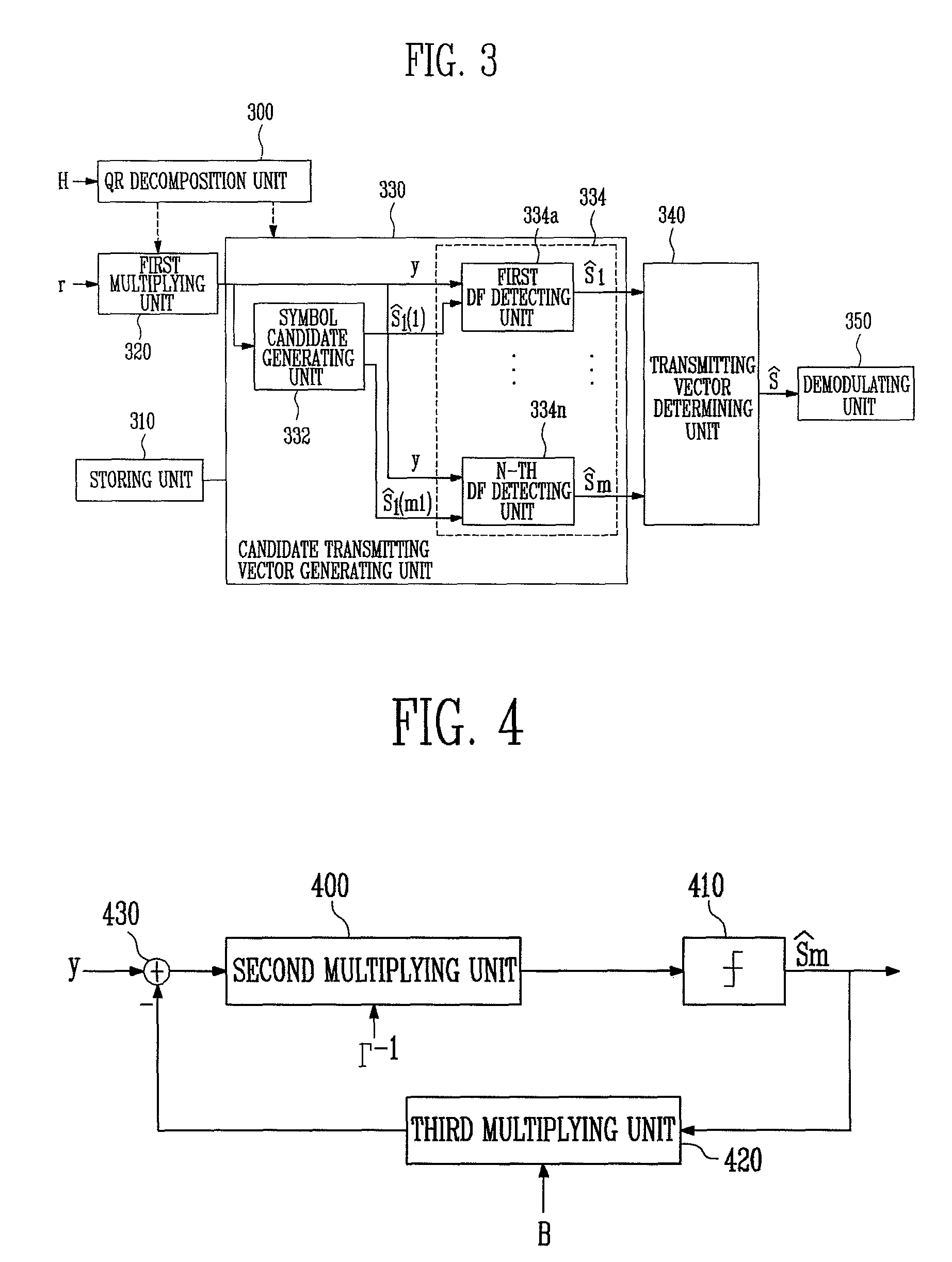
[0030]FIG. 2 illustrates a schematic configuration of a MIMO communication system using V-BLAST according to the present invention, FIG. 3 illustrates a schematic configuration of a receiver shown in FIG. 2, and FIG. 4 illustrates a schematic configuration of a DF detecting unit shown in FIG. 3.

[0031]Referring to FIG. 2, a MIMO communication system using V-BLAST includes a transmitter 200 and a receiver 210.

[0032]The transmitter 200 applies a different modulation system and power allocation coefficient for each antenna to data to be transmitted.

[0033]The transmitter 200 includes a modulating unit 202 for modulating data to be...


PUM


Abstract

Provided is a receiver of a multi-input multi-output system using multiple antennas, the receiver including: a first multiplying unit for multiplying a vector r received via the antenna by a Hermitian matrix Q; a candidate transmitting vector generating unit for detecting a signal on a lowest modulation order transmitting antenna from the received vector y output from the first multiplying unit, creating as many symbol candidates as the modulation order of the detected signal, and generating a candidate transmitting vector using each symbol candidate; a transmitting vector determining unit for obtaining a distance between each candidate transmitting vector generated by the candidate transmitting vector generating unit and the received vector y to determine a final transmitting vector; and a demodulating unit for demodulating the final transmitting vector determined by the transmitting vector determining unit. Since the receiver detects a transmitting vector with reference to a signal on a lowest modulation order transmitting antenna, the receiver can have a simpler structure.

Description

CROSS-REFERENCE TO RELATED APPLICATION[0001]This application claims priority to and the benefit of Korean Patent Application No. 2006-49370, filed Jun. 1, 2006, the disclosure of which is incorporated herein by reference in its entirety.BACKGROUND[0002]1. Field of the Invention[0003]The present invention relates to a multi-input multi-output system and a method for demodulating a transmitting vector in a receiver of the system in which the receiver detects a transmitting vector from a received vector received via multiple antennas and demodulates the detected transmitting vector.[0004]2. Discussion of Related Art[0005]A radio channel having a multi-path is known to have high channel capacity, and it is expected that multi-input multi-output (MIMO) systems will be widely used in the future. In an MIMO system, proper space-time processing provides ample multi-path scattering on a communication channel, as is already known.[0006]The Diagonal-Bell Labs Layered Space-Time (D-BLAST) syste...

Claims


Application Information

Patent Timeline
Patent Type & Authority Patents(United States)
IPC IPC(8): H04K1/10H04L1/02H04L27/28H04B7/02H04B7/08
CPCH04B7/0434H04B7/0413H04L1/0656H04W52/42
Inventor KIM, TAE JOONEO, IK SOOKIM, HYOUN KUKPARK, HYUN CHEOL
Owner ELECTRONICS & TELECOMM RES INST
Learn More