
Wavelength selective reconfigurable optical cross-connect

a cross-connect switch and wavelength selective technology, applied in the field of optical communication network systems, can solve the problems of increasing the bandwidth of fiber optic communication networks, not being able to cope with this demand, and increasing the demand for network functionality

Active Publication Date: 2010-08-31
II VI DELAWARE INC
View PDF23 Cites 48 Cited by
  • Summary
  • Abstract
  • Description
  • Claims
  • Application Information

AI Technical Summary

Benefits of technology

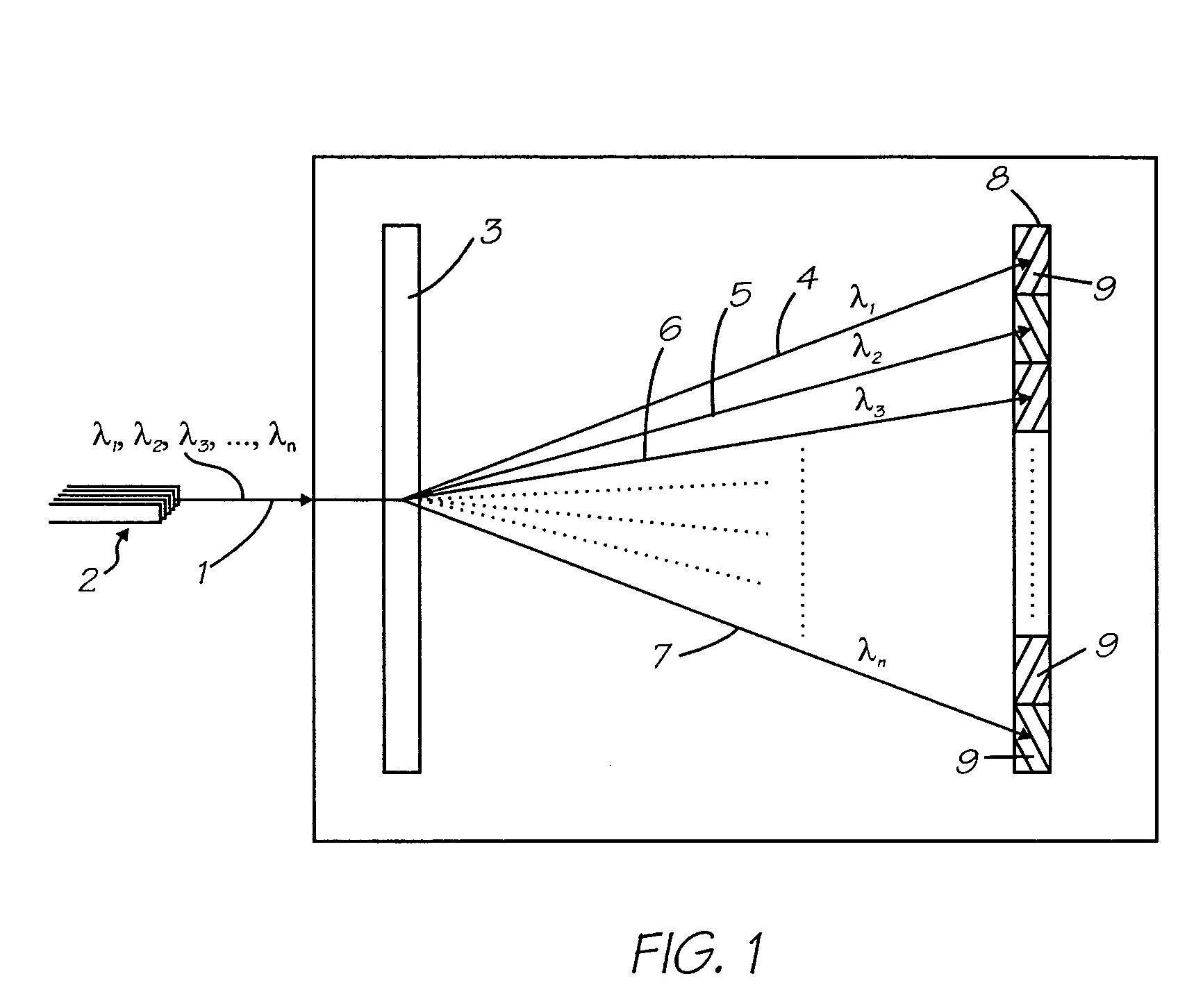
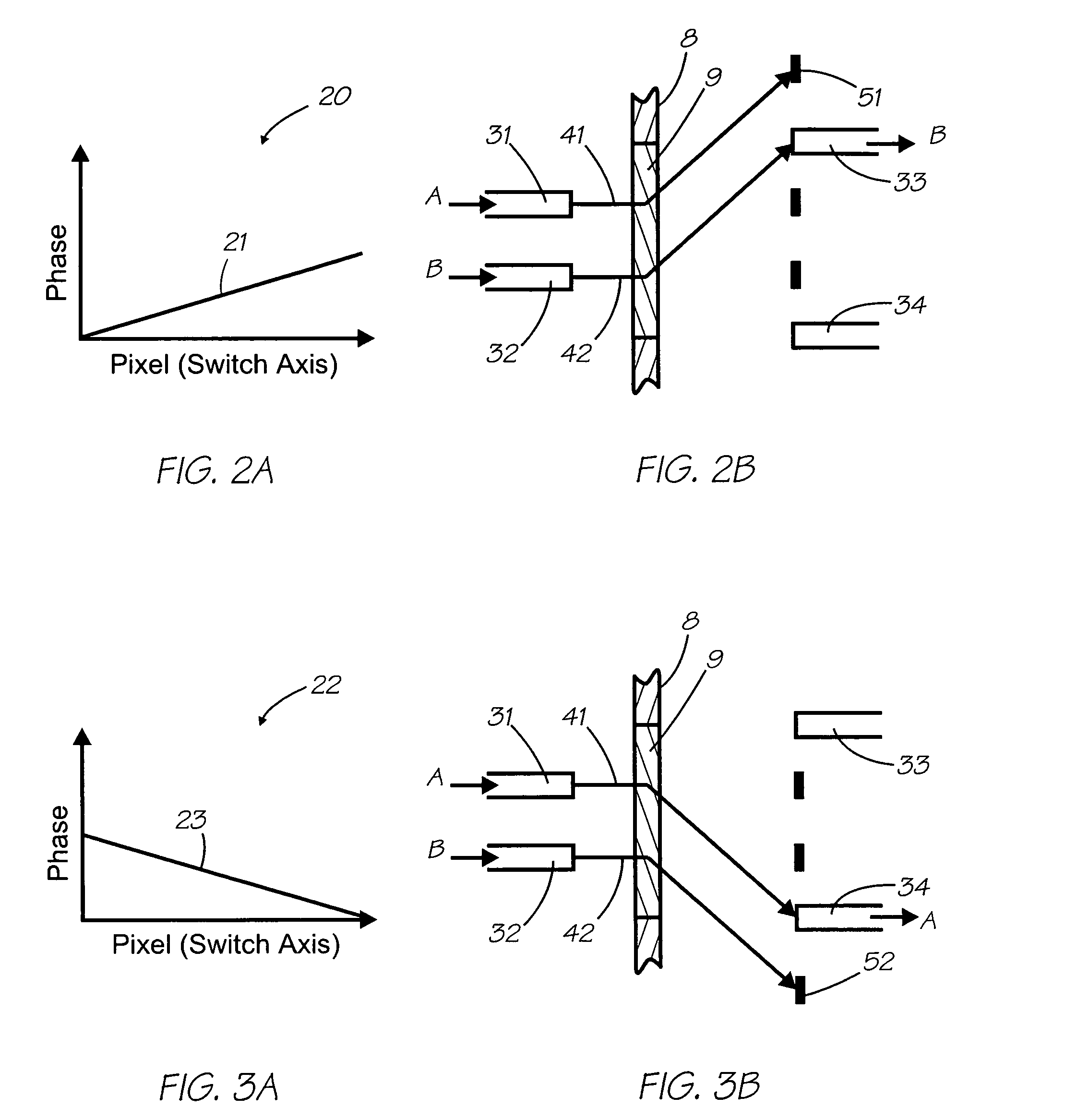
The present invention provides a system and method for a reconfigurable all-optical wavelength selective OXC switch that can route wavelength channels to desired output ports without blocking any other channels. The switch includes a wavelength dispersion element that separates the wavelength channels in an optical input signal beam, an optical phased-matrix coupling device with independently modulateable pixels, and a diffraction grating or prism for wavelength dispersion. The optical signals are then directed onto the phased-matrix coupling device, which can simultaneously route a wavelength channel to multiple output ports or direct it to a null state. The system and method provide a flexible and efficient solution for routing optical signals and have applications in optical communication and optical sensing.

Problems solved by technology

The increased bandwidth of fiber optic communication networks is still often insufficient to cope with this demand without utilizing the ability of these fibers to carry large numbers of individual communication channels, each identified by the particular wavelength of the light.
The disadvantage of this technique is that the increasing density of wavelength channels places increasing demand on network functionality for connecting the individual channels to individual destination points on a dynamic basis, and for the ability to add or drop an individual wavelength channel into or out of the optical signal.
These systems, however, generally route all the channels contained in the signal appearing on the input ports to one of the output ports, often without the ability to block an input completely.

Method used


Image

  • Wavelength selective reconfigurable optical cross-connect
  • Wavelength selective reconfigurable optical cross-connect
  • Wavelength selective reconfigurable optical cross-connect

Examples


Embodiment Construction

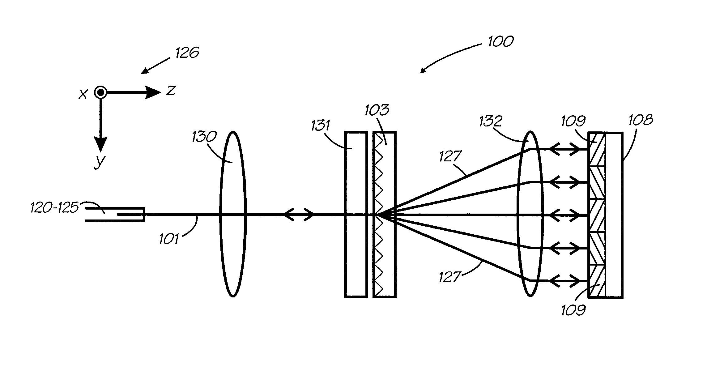
[0079]The reconfigurable wavelength selective OXC device includes at least two input ports, a number of output ports at least equal to the number of inputs and a means for routing at least one optical channel, distinguished by its center wavelength, contained in an input signal to at least one output. The optical channel is usually distinguished by its center wavelength, however this is not the only method available.

[0080]The routing means includes:[0081]a plurality of optical ports for carrying optical signal beams;[0082]a wavelength dispersion element for spatially separating the plurality of wavelength channels contained in the optical signal beams;[0083]method for creating an optical overlap between the projections from at least three selected optical ports for coupling a particular wavelength channel originating at one port to at least two other ports, where one, all or none of the other ports corresponds to a null state.

[0084]The device in the preferred embodiment is a reconfi...


PUM


Abstract

An optical coupling device including: at least a first input port for delivering an optical input signal beam that includes a plurality of wavelength channels; at least a first optical output port for receiving an optical output signal beam; a wavelength dispersion element for spatially separating the plurality of wavelength channels in the optical input signal beam to form a plurality of spatially separated wavelength channel beams; an optical coupling device for independently modifying the phase of each of the spatially separated wavelength channel beams such that, for at least one wavelength channel beam, a selected fraction of the light is coupled to the first output port and a fraction of the light is coupled away from the first output port.

Description

FIELD OF THE INVENTION[0001]The current invention relates to optical communications network systems, and in particular a device and method that provides for a reconfigurable wavelength selective reconfigurable optical cross-connect switch.BACKGROUND OF THE INVENTION[0002]The recent growth in the demand for broadband services has resulted in a pressing need for increased capacity on existing communication channels. The increased bandwidth of fiber optic communication networks is still often insufficient to cope with this demand without utilizing the ability of these fibers to carry large numbers of individual communication channels, each identified by the particular wavelength of the light. This technique is known as dense wavelength division multiplexing (DWDM). The disadvantage of this technique is that the increasing density of wavelength channels places increasing demand on network functionality for connecting the individual channels to individual destination points on a dynamic ...

Claims


Application Information

Patent Timeline
Patent Type & Authority Patents(United States)
IPC IPC(8): G02B6/26G02B5/32H04J14/02
CPCG02B6/272G02B6/2793G02B6/2931G02B6/29311G02B6/29313G02B6/29395G02B6/29397
Inventor FRISKEN, STEVEN JAMESBAXTER, GLENN WAYNEZHOU, HAOABAKOUMOV, DMITRI
Owner II VI DELAWARE INC
Learn More