Method and system for virtual on-demand recovery for real-time, continuous data protection

a data protection and real-time recovery technology, applied in the field of enterprise data protection, can solve the problems of staggering costs, data loss, data recovery, and the cost of “code red” virus alone, and achieve the effect of facilitating the data protection servi

Active Publication Date: 2010-08-31
QUEST SOFTWARE INC
View PDF224 Cites 60 Cited by
  • Summary
  • Abstract
  • Description
  • Claims
  • Application Information

AI Technical Summary

Benefits of technology

[0012]A data management system or “DMS” provides an automated, continuous, real-time, substantially no downtime data protection service to one or more data sources associated with a set of application host servers. The data management system typically comprises one or more regions, with each region having one or more clusters. A given cluster has one or more nodes that share storage. To facilitate the data protection service, a host driver embedded in an application server captures real-time data transactions, preferably in the form of an event journal that is provided to a DMS cluster. The driver functions to translate traditional file / database / block I / O and the like into a continuous, application-aware, output data stream. The host driver includes an event processor that provides the data protection service. In particular, the data protection is provided to a given data source in the host server by taking advantage of the continuous, real-time data that the host driver is capturing and providing to other DMS components.

Problems solved by technology

A critical information technology (IT) problem is how to cost-effectively deliver network wide data protection and rapid data recovery.
The “code red” virus alone cost an estimated $2.8 B in downtime, data loss, and recovery.
The reason for these staggering costs is simple—traditional schedule based tape and in-storage data protection and recovery approaches can no longer keep pace with rapid data growth, geographically distributed operations, and the real time requirements of 24×7×365 enterprise data centers.
First, changes in data occurring after a backup or snapshot is taken are always at risk and may be lost.
Second, tape backup requires that the host application be shutdown or be put into a backup mode for a long time period until the complete data set is copied to tape.
Third, as the data size grows, the bandwidth required to offload data repeatedly and the attendant storage required to store the complete snapshots can become impractical quickly.
Further, during a “hot” snapshot critical data can change, which may result in an incomplete update being captured (e.g., only one portion of a transaction) such that, when reintroduced, the data is not fully consistent.
Most importantly, storage based snapshot does not capture fine grain application data and, therefore, it cannot recover fine grain application data objects without reintroducing (i.e. recovering) the entire backup volume to a new application computer server to extract the fine grain data object.
Data recovery on a conventional data protection system is a tedious and time consuming operation.
As these separate and distinct processes and systems are carried out, there are significant periods of application downtime.

Method used


Image

  • Method and system for virtual on-demand recovery for real-time, continuous data protection
  • Method and system for virtual on-demand recovery for real-time, continuous data protection
  • Method and system for virtual on-demand recovery for real-time, continuous data protection

Examples


Embodiment Construction

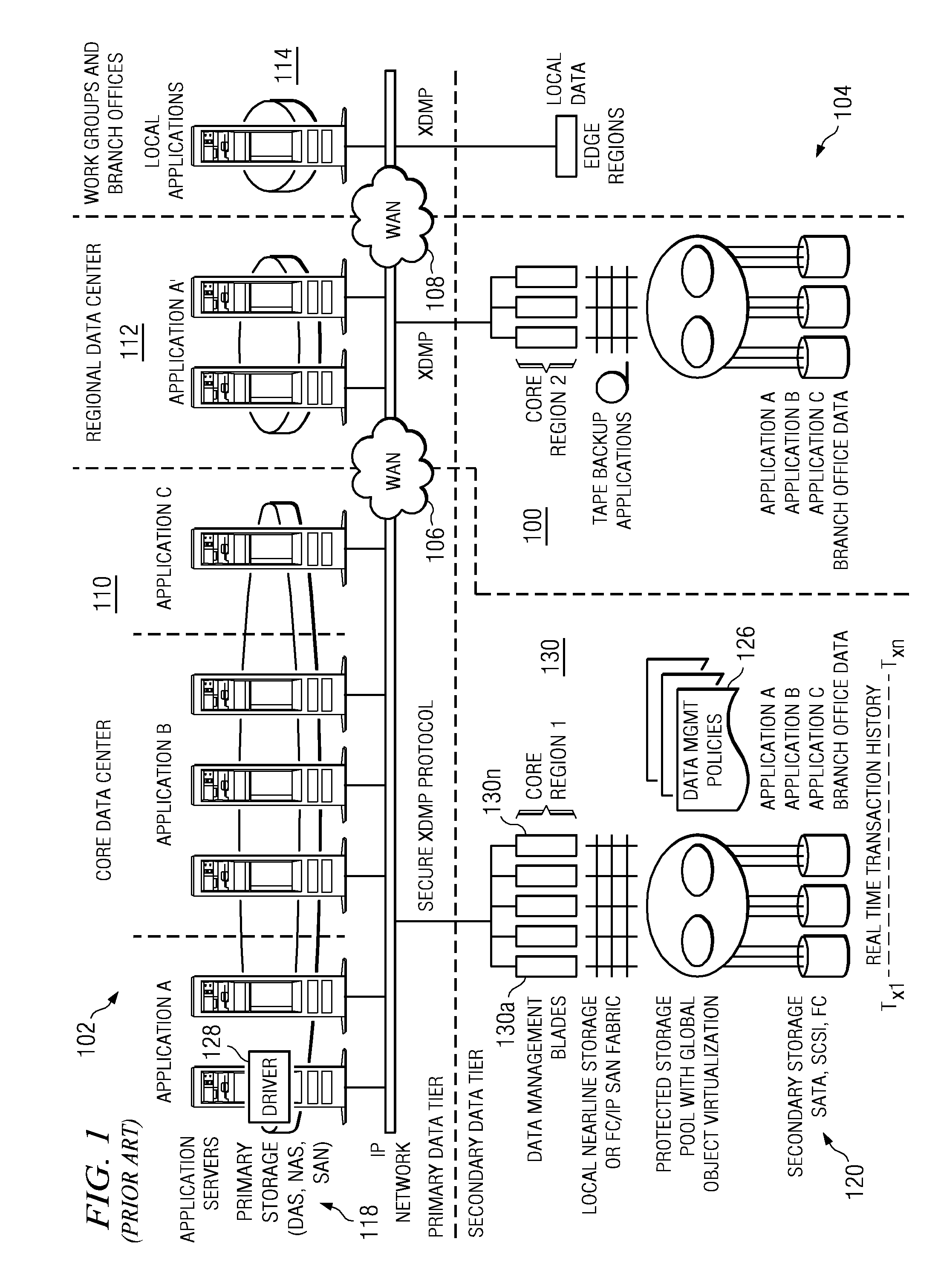
[0034]FIG. 1 illustrates a representative enterprise 100 in which the present invention may be implemented. This architecture is meant to be taken by way of illustration and not to limit the applicability of the present invention. In this illustrative example, the enterprise 100 comprises a primary data tier 102 and a secondary data tier 104 distributed over IP-based wide area networks 106 and 108. Wide area network 106 interconnects two primary data centers 110 and 112, and wide area network 108 interconnects a regional or satellite office 114 to the rest of the enterprise. The primary data tier 102 comprises application servers 116 running various applications such as databases, email servers, file servers, and the like, together with associated primary storage 118 (e.g., direct attached storage (DAS), network attached storage (NAS), storage area network (SAN)). The secondary data tier 104 typically comprises one or more data management server nodes, and secondary storage 120, whi...


PUM


Abstract

A data management system or “DMS” provides an automated, continuous, real-time, substantially no downtime data protection service to one or more data sources associated with a set of application host servers. To facilitate the data protection service, a host driver embedded in an application server captures real-time data transactions, preferably in the form of an event journal that is provided to other DMS components. The driver functions to translate traditional file/database/block I/O and the like into a continuous, application-aware, output data stream. The host driver includes an event processor. When an authorized user determines that a primary copy of the data in the host server has become incorrect or corrupted, the event processor can perform a recovery operation to an entire data source or a subset of the data source using former point-in-time data in the DMS. The recovery operation may have two phases. First, the structure of the host data in primary storage is recovered to the intended recovering point-in-time. Thereafter, the actual data itself is recovered. The event processor enables such data recovery in an on-demand manner, in that it allows recovery to happen simultaneously while an application accesses and updates the recovering data.

Description

CROSS-REFERENCE TO RELATED APPLICATIONS[0001]This application is related to commonly-owned applications:[0002]Ser. No. 10 / 841,398, filed May 7, 2004, and titled “METHOD AND SYSTEM FOR AUTOMATED, NO DOWNTIME, REAL-TIME, CONTINUOUS DATA PROTECTION.”[0003]Ser. No. 10 / 842,286, filed May 10, 2004, and titled “METHOD AND SYSTEM FOR REAL-TIME EVENT JOURNALING TO PROVIDE ENTERPRISE DATA SERVICES.”[0004]Ser. No. 10 / 863,117, filed Jun. 8, 2004, and titled “METHOD AND SYSTEM FOR NO DOWNTIME, REAL-TIME, CONTINUOUS DATA PROTECTION.”[0005]Ser. No. 10 / 862,971, filed Jun. 8, 2004, and titled “METHOD AND SYSTEM FOR NO DOWNTIME, RESYNCHRONIZATION FOR REAL-TIME, CONTINUOUS DATA PROTECTION.”BACKGROUND OF THE INVENTION[0006]1. Technical Field[0007]The present invention relates generally to enterprise data protection.[0008]2. Background of the Related Art[0009]A critical information technology (IT) problem is how to cost-effectively deliver network wide data protection and rapid data recovery. In 2002, f...

Claims


Application Information

Patent Timeline
Patent Type & Authority Patents(United States)
IPC IPC(8): G06F11/00
CPCG06F11/1471G06F11/2097G06F11/2094G06F2201/82G06F11/1469G06F2201/84
Inventor SIM-TANG, SIEW YONG
Owner QUEST SOFTWARE INC
Why Eureka
Try Eureka