Air-bleed gas turbine

a gas turbine and air bleed technology, applied in the field of gas turbines, can solve the problems of unstable combustion in the combustor, difficulty in bleeding a large amount of compressed air, uneven distribution of compressed air supplied to the combustor, etc., and achieve the effect of effective and stably rotating the upstream turbine disk

Inactive Publication Date: 2010-09-07
TOYOTA JIDOSHA KK
View PDF11 Cites 4 Cited by
  • Summary
  • Abstract
  • Description
  • Claims
  • Application Information

AI Technical Summary

Benefits of technology

[0016]With the air-bleed gas turbines according to the aforementioned aspects of the invention, it is possible to bleed a large amount of compressed air, which is delivered under pressure from the compressor, into the air bleed port. Even in this case, it is still possible to supply the compressed air to the combustor uniformly in the circumferential direction of the combustor, whereby the combustion gas is produced in the combustor uniformly in the circumferential direction of the combustor. The uniformly produced combustion gas makes it possible to effectively and stably rotate the upstream turbine disk and the downstream turbine disk.

Problems solved by technology

This configuration makes it difficult to bleed a large amount of compressed air.
However, with this configuration, there is a possibility that the pressure distribution of the compressed air that is supplied to the combustor is uneven because the pressure around the air bleed port decreases, resulting in unstable combustion in the combustor.

Method used


Image

  • Air-bleed gas turbine
  • Air-bleed gas turbine
  • Air-bleed gas turbine

Examples


first embodiment

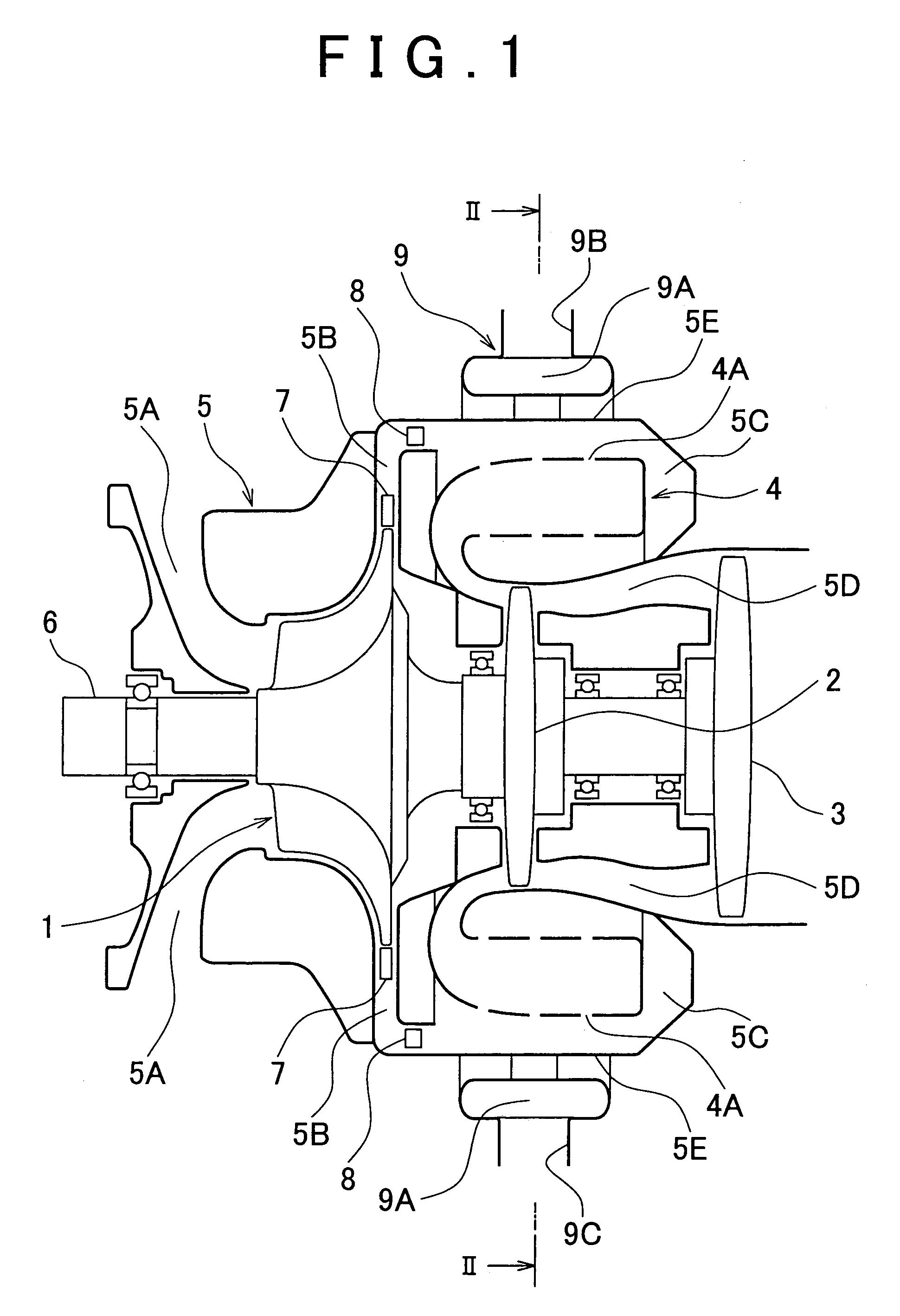
[0037]In the thus configured air-bleed gas turbine according to the invention, the air sucked from the air supply passage 5A is compressed and delivered under pressure to the compressed air passage 5B due to rotation of the compressor impeller 1 shown in FIG. 1. The pressure of the compressed air is gradually increased by the diffuser 7 disposed in the upstream side of the compressed air passage 5B. Then, the flow of the compressed air is adjusted by the deswirl vane 8 to a flow that proceeds straight toward the circular space 5C, and then supplied into the circular space 5C. The deswirl vane 8 is provided in the L-sectioned downstream-side end portion of the compressed air passage 5B.

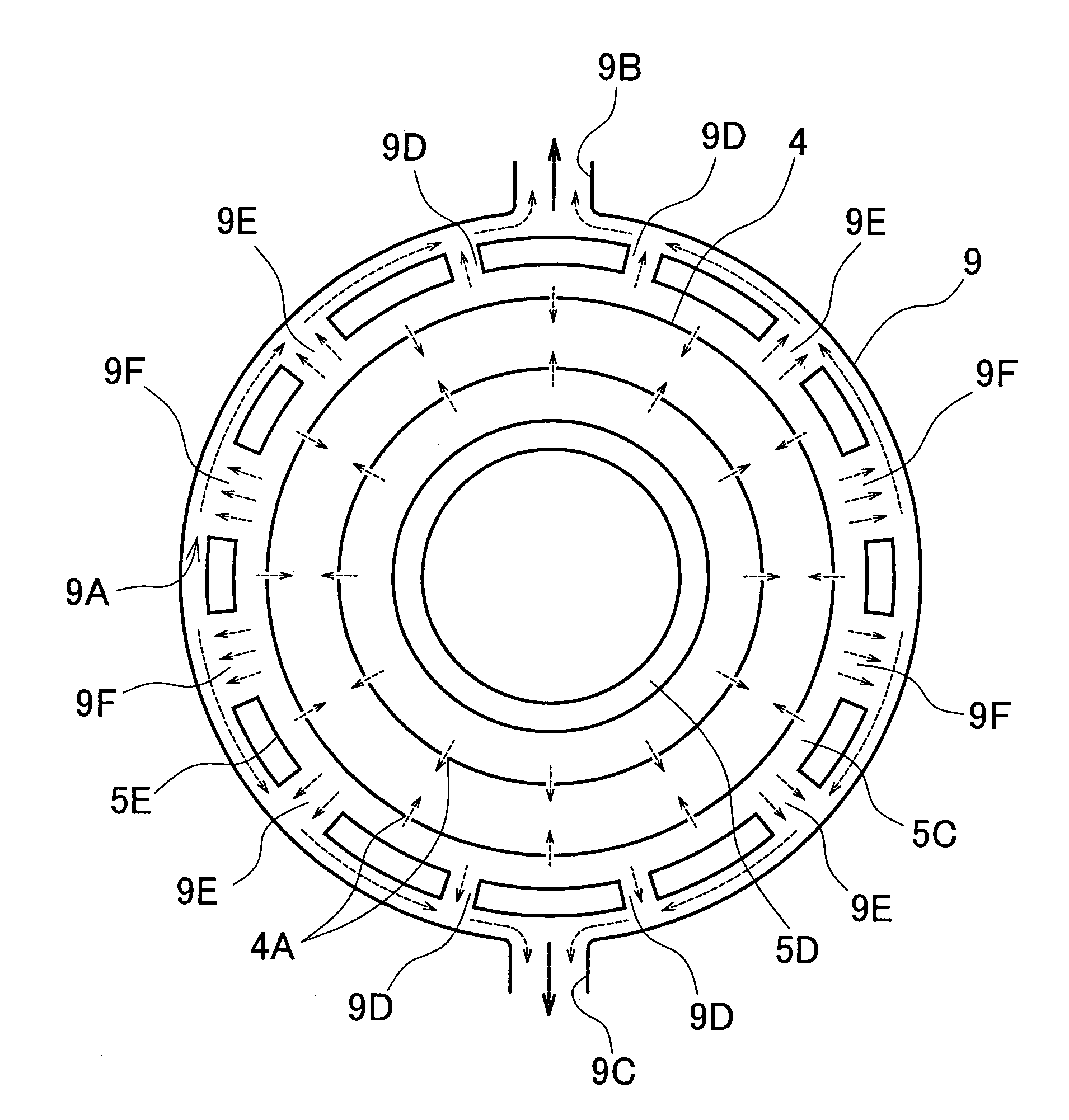
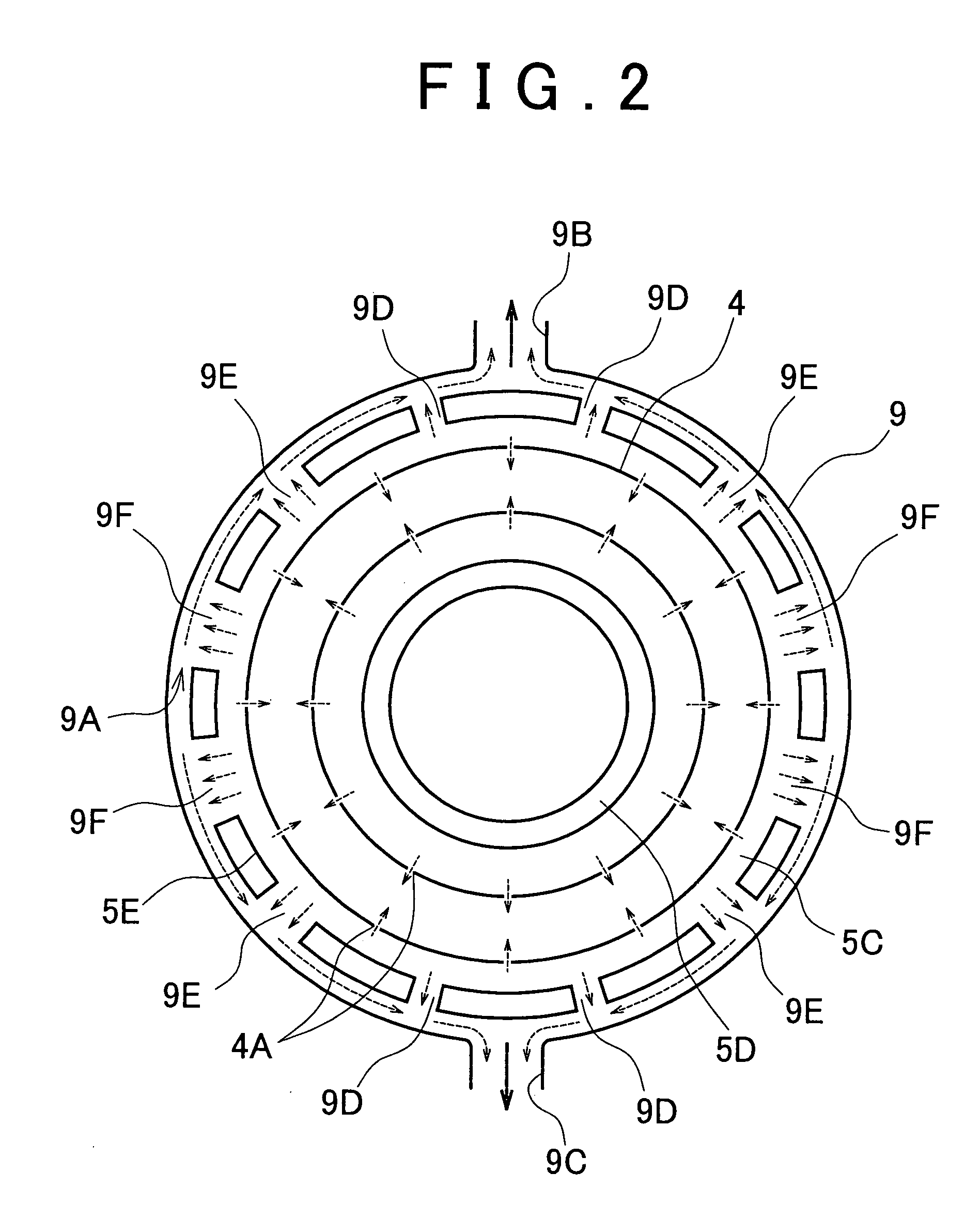
[0038]As shown in FIG. 2, some compressed air supplied to the circular space 5C flows into the combustor 4 through the compressed air inlet holes 4A formed in the periphery of the combustor 4, and the remaining compressed air supplied to the circular space 5C flows into the air bleed passage 9A through...

second embodiment

[0050]In the thus configured air-bleed gas turbine according to the invention, when the compressed air is supplied into the circular space 5C due to rotation of the compressor impeller 1 shown in FIG. 3, some of the supplied compressed air is supplied into the combustor 4 through the compressed air inlet holes 4A, and the remaining compressed air is supplied into the circular air bleed passage 11 through the communication passages A, B, C, and is bled to a device outside the gas turbine through the air bleed ports 5G and 5H, as shown in FIG. 5.

[0051]As described above, the backpressure is increased as the distance from the air bleed port 9B or 9C increases. That is, the backpressure around the communication passage B is higher than that around the communication passage A, and the backpressure around the communication passage C is higher than that around the communication passage B. Therefore, the communication passages A, B and C are formed in such a manner that the flow passage are...


PUM


Abstract

An air-bleed gas turbine includes a compressor; a combustor; a turbine; and an air bleed portion by which compressed air, which is supplied from the compressor to a circular space that surrounds the combustor, is partially supplied to a device outside the air-bleed gas turbine. The air bleed portion includes an air bleed passage that is communicated with an air bleed port which is connected to the device outside the air-bleed gas turbine, and a communication passage that is communicated with the circular space. The air bleed passage is communicated with the circular space through the communication passage. The flow passage area of the communication passage is increased as the distance from the air bleed port increases in the circumferential direction of the circular space.

Description

INCORPORATION BY REFERENCE[0001]The disclosure of Japanese Patent Application No. JP2007-169393 filed on Jun. 27, 2007 including the specification, drawings and abstract is incorporated herein by reference in its entirety.BACKGROUND OF THE INVENTION[0002]1. Field of the Invention[0003]The invention relates generally to a gas turbine, and, more specifically to an air-bleed gas turbine that includes air bleed means through which the compressed air, which is supplied from a compressor toward a combustor, is partially supplied to a device outside the gas turbine.[0004]2. Description of the Related Art[0005]An air-bleed gas turbine, which is one type of gas turbine, is in common use recently. The air-bleed gas turbine includes air bleed means, such as an air bleed port, an air bleed pipe, and an air bleed duct, through which the compressed air, supplied from a compressor toward a combustor, is partially supplied to a device outside the gas turbine.[0006]Japanese Patent Application Public...

Claims


Application Information

Patent Timeline
Patent Type & Authority Patents(United States)
IPC IPC(8): F02C6/04F02C6/08
CPCF01D9/045F02C3/145F02C6/08F05D2250/52F04D29/4206
Inventor TATEBAYASHI, YASUSHI
Owner TOYOTA JIDOSHA KK
Why Eureka
Try Eureka