Omni indexing mount primarily for attaching a noise suppressor or other auxiliary device to a firearm

Inactive Publication Date: 2010-09-07
JJE BRANDS LLC
View PDF4 Cites 51 Cited by
  • Summary
  • Abstract
  • Description
  • Claims
  • Application Information

AI Technical Summary

Benefits of technology

[0008]The present invention provides an apparatus and method for reliably attaching and repeatedly indexing a noise suppressor to the muzzle end of a firearm, and for easily removing such device there from. The present invention utilizes the wrench flats present on most flash hiders or other muzzle devices to provide a mating surface. which also serves as

Problems solved by technology

The HALO fails to provide a mechanical method for indexing the silencer repeatedly between uses creati

Method used


Image

  • Omni indexing mount primarily for attaching a noise suppressor or other auxiliary device to a firearm
  • Omni indexing mount primarily for attaching a noise suppressor or other auxiliary device to a firearm
  • Omni indexing mount primarily for attaching a noise suppressor or other auxiliary device to a firearm

Examples


Embodiment Construction

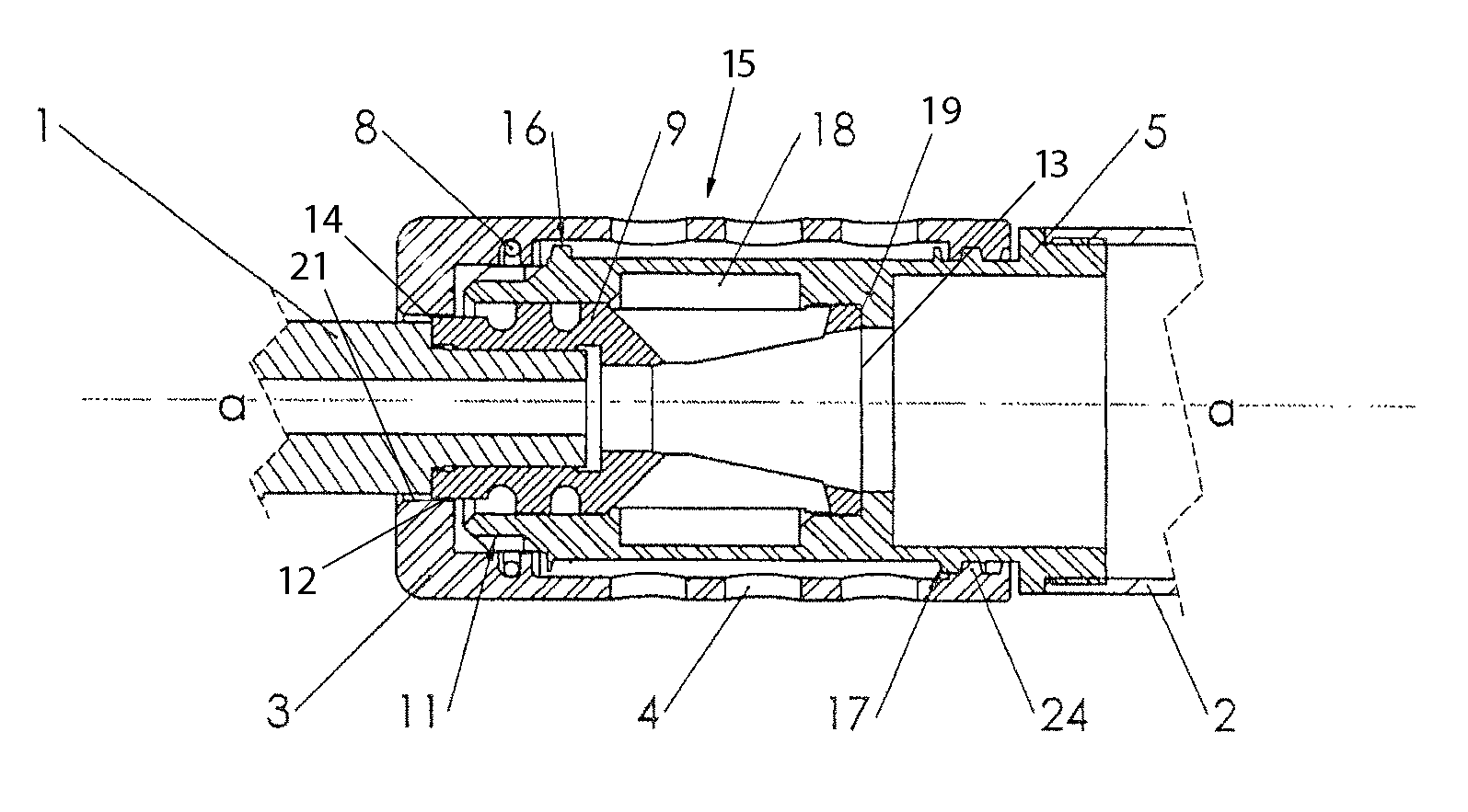
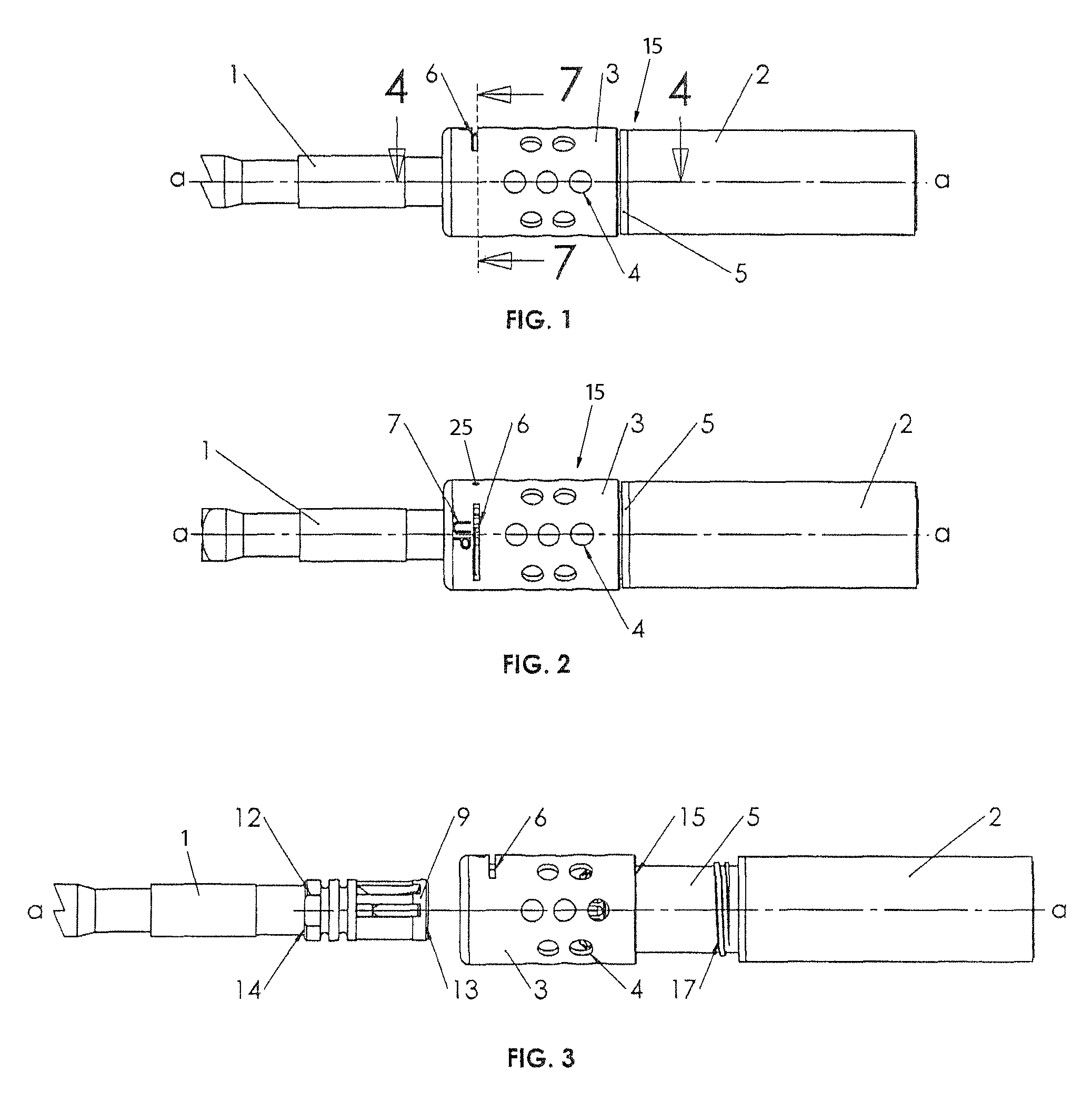
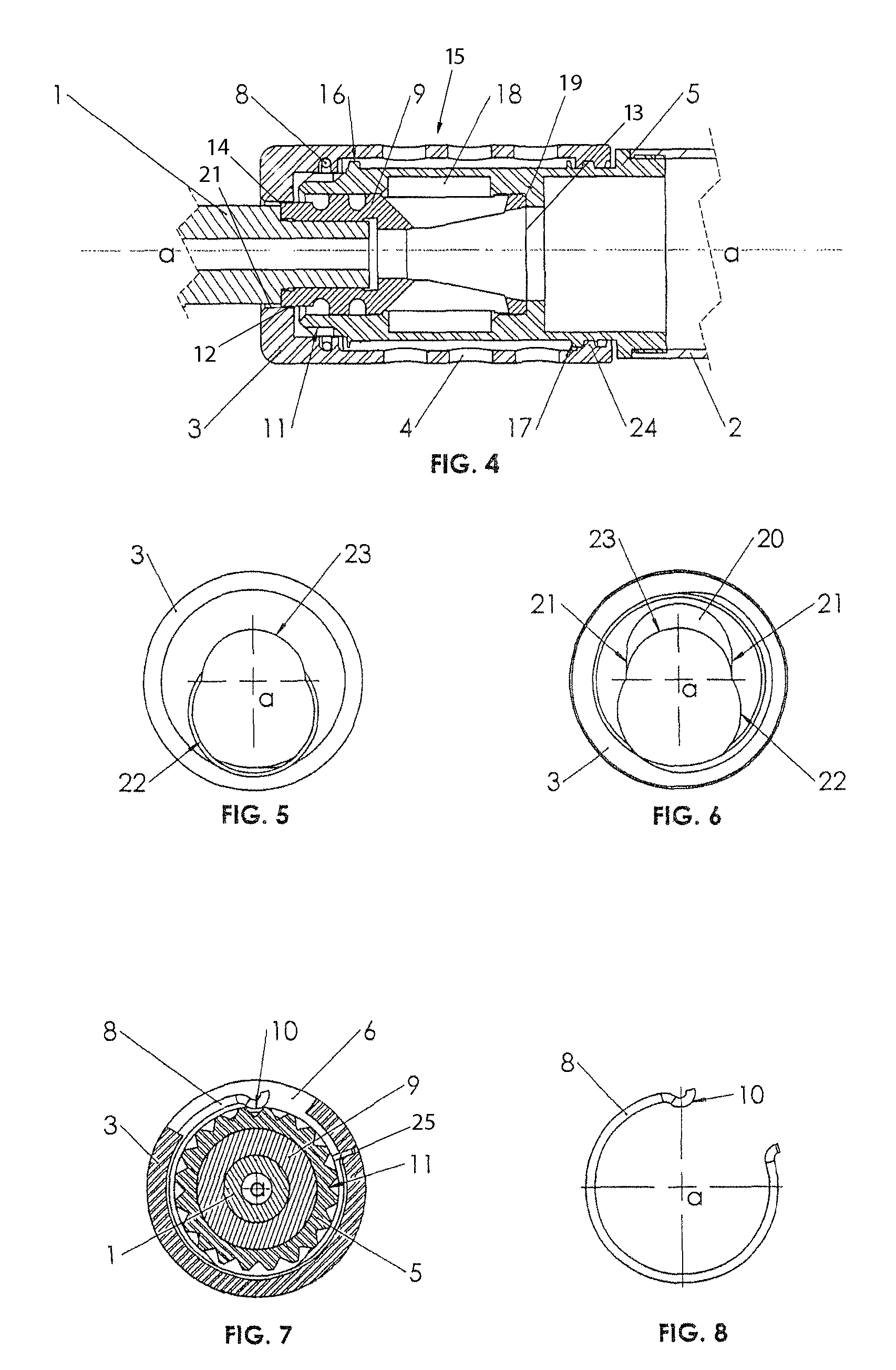
[0021]Starting with FIG. 1, there is an illustration of a barrel 1, an auxiliary device 2 (preferred embodiment noise suppressor 2), and the proposed mounting system 15 encompassing the rear cap 3, weight relief apertures 4, orientation indicator 7, mount 5 and the spring relief slot 6. The longitudinal axis is represented as a.

[0022]In FIG. 2, there is illustrated a top view of barrel 1, preferred embodiment noise suppressor 2, and the proposed mounting system 15 encompassing the rear cap 3, weight relief apertures 4, orientation indicator 7, mount 5 and the spring relief slot 6. The laser engraved orientation indicator (“up”) 7 is used to orient the preferred embodiment of the noise suppressor 2 every time.

[0023]In FIG. 3, there is illustrated a side view of the proposed mounting system 15 in a second position showing how the mounting system 15 the preferred embodiment noise suppressor 2, barrel 1, and a fixture 9 such as a flash compensator 9 appear before installation occurs. Th...


PUM


Abstract

An apparatus and method for easily, and reliably attaching a noise suppressor or other auxiliary device to a standard A2 flash compensator typically located at the muzzle end of a firearm barrel and for easily, and reliably removing the noise suppressor or other auxiliary device there from through the novel ideal of providing an apparatus which consistently indexes a noise suppressor on the wrench flats of a standard A2 flash hider.

Description

BACKGROUND OF THE INVENTION[0001]1. Field of Invention[0002]This invention generally relates to firearms, specifically to systems for attaching a noise suppressor or other device to a 22 mm flash hider with wrench flats similar to that which is typically found on the United States military M16 rifles.[0003]2. Prior Art[0004]Previous systems exist for attaching noise suppressors to a firearm, and specifically for using a flash hider or other muzzle device as a mount for the noise suppressor. Gemtech, a silencer manufacturer, produces a product named “HALO” which also attaches to a standard U.S. military A2 flash hider. The HALO fails to provide a mechanical method for indexing the silencer repeatedly between uses creating a situation where the host firearms point of impact is variable each time the silencer is remounted. There is a need for a reliable, secure attachment system for mounting noise suppressors to a firearm, particularly a non proprietary flash hider, specifically the st...

Claims


Application Information

Patent Timeline
IPC IPC(8): F41A21/00
CPCF41A21/30F41A21/325
Inventor BRITTINGHAM, KEVIN TYSON
Owner JJE BRANDS LLC
Why Eureka
Try Eureka