Electrical contact with overlapping structure

a technology of electrical contact and overlapping structure, applied in the field of electrical contact, can solve the problems of low production efficiency, low productivity of electrical contact, cylindrical shape of lower contact pin, etc., and achieve the effect of easy production and assembly

Active Publication Date: 2010-09-07
HON HAI PRECISION IND CO LTD
View PDF13 Cites 17 Cited by
  • Summary
  • Abstract
  • Description
  • Claims
  • Application Information

AI Technical Summary

Benefits of technology

[0007]An object of the present invention is to provide an electrical contact with an overlapping structure for connecting electronic devices, which is easily produced and assembled.

Problems solved by technology

Firstly, the upper and the lower contact pins are of cylindrical shape, and are not easy to manufacture.
Secondly, the lower contact pin, the spring and the upper contact pin should be assembled in the pipe body orderly, so that it is difficult to assemble the components for such a complicated assembling process, thus productivity of the electrical contact is low.
Thirdly, the openings are easy to be abraded by the high-frequently-encountered friction between the two contact pins and the pipe body.
Furthermore, manufacturing cost of the electrical contact is high due to a large amount of machining work.

Method used


Image

  • Electrical contact with overlapping structure
  • Electrical contact with overlapping structure
  • Electrical contact with overlapping structure

Examples


Embodiment Construction

[0014]Reference will now be made to the drawing figures to describe the preferred embodiments of the present invention in detail.

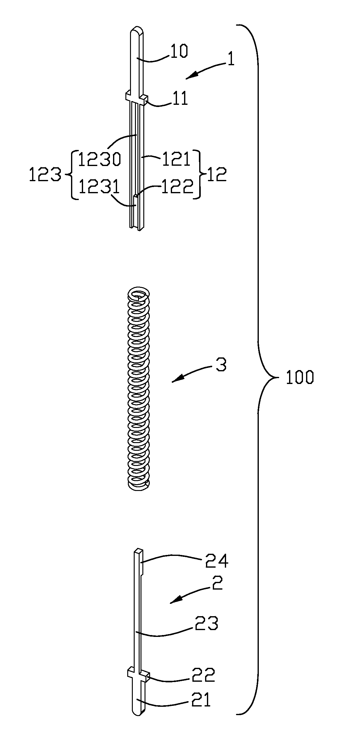
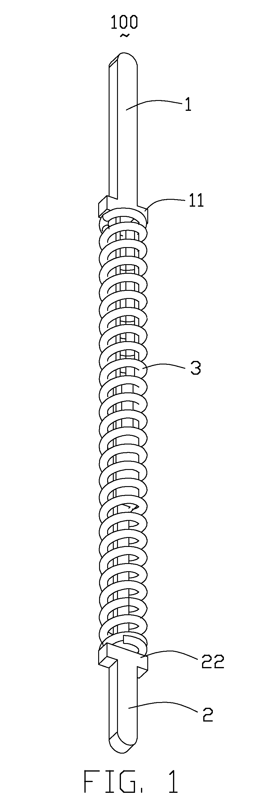
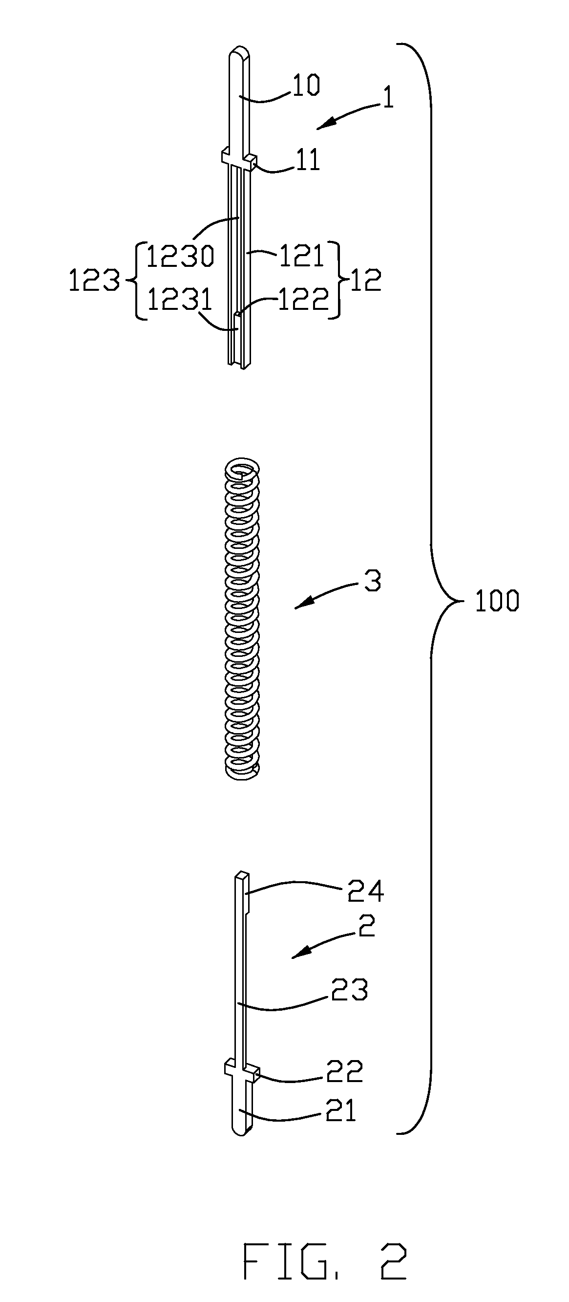
[0015]Referring to FIGS. 1 to 4, an electrical contact 100 in accordance with the present invention is adapted for being arranged in a test socket or a burn-in socket for receiving an IC and electrically connecting the IC to a PCB. In such a state, the test socket performs a test to the IC. The electrical contact 100 comprises a first contact pin 1, a second contact pin 2 and an elastic member 3 fitted over a predetermined area between the first contact pin 1 and the second contact pin 2.

[0016]As shown in FIG. 2, the first contact pin 1 stamped from a sheet metal includes a slender contacting portion 10 with a sharp top end for contacting with the IC. A pair of first projecting portions 11 are provided on lateral sides of a bottom end of the contacting portion 10 for limiting the elastic member 3. The first projecting portions 11 are vertical to the contac...


PUM


Abstract

An electrical contact includes a first contact pin, a second contact pin and an elastic member surrounding the first contact pin and the second contact pin. Both of the first contact pin and the second contact pin include contacting portions. The first contact pin has a guiding portion including two lead-in arms and a stop portion between the two leading arms. The second contact has a main body and a protrusion on a top end of the main body. The leading arms define a guiding groove therebetween for the main body of the second contact pin moving up and down. The protrusion abuts against the stop portion of the first contact pin to prevent the second contact from sliding out of the guiding groove.

Description

BACKGROUND OF THE INVENTION[0001]1. Field of the Invention[0002]The present invention relates generally to an electrical contact for electronic devices, and more particularly to an electrical contact with overlapping structure for electrically connecting a lead of an integrated circuit (IC) to a corresponding pad of a printed circuit board (PCB).[0003]2. Description of the Related Art[0004]U.S. Pat. No. 7,025,602 issued to Hwang on Apr. 11, 2006, discloses a conventional contact which comprises an upper and a lower contact pins and a spring. The upper and the lower contact pins and the spring are all arranged uprightly in a line and received in. The spring is arranged between the upper and the lower contact pins and provides a repellent force for those two contact pins to move away from each other. A top end of the upper contact pin and a bottom end of the lower contact pin project out of two opening defined on two opposite ends of the pipe body respectively. The openings are dimens...

Claims


Application Information

Patent Timeline
Patent Type & Authority Patents(United States)
IPC IPC(8): H01R12/00
CPCG01R1/06722H01R13/2421H01R2201/20
Inventor HSIEH, WEN-YIHSIAO, SHIH-WEI
Owner HON HAI PRECISION IND CO LTD
Why Eureka
Try Eureka