Control device and control method for continuously variable transmission

a control device and transmission technology, applied in the direction of gearing details, hoisting equipment, instruments, etc., can solve the problems of inability to detect the current speed ratio using these parameters, and the belt may deteriorate, so as to prevent the slippage of the belt and ensure the starting performance of the vehicle.

Active Publication Date: 2010-09-07
JATCO LTD +1
View PDF16 Cites 9 Cited by
  • Summary
  • Abstract
  • Description
  • Claims
  • Application Information

AI Technical Summary

Benefits of technology

[0010]The present invention has been designed in order to solve these problems, and it is an object thereof to enable accurate estimation of a current speed ratio when a vehicle is stationary and control is underway to shift the speed ratio toward a low side speed ratio while a primary pulley and a secondary pulley are in a non-rotational state, and also to prevent belt slippage and ensure the starting performance of the vehicle when a start request is issued to the vehicle during this control.
[0013]According to this invention, when the vehicle is stationary, the current speed ratio can be estimated accurately during control to shift the speed ratio toward the low side speed ratio while the primary pulley and secondary pulley are in a non-rotational state, and when a drive request is issued to the vehicle during this control, the primary pulley pressure can be supplied on the basis of the estimated current speed ratio. As a result, belt slippage can be prevented and the starting performance of the vehicle can be ensured.

Problems solved by technology

In the inventions described above, however, when the speed ratio is shifted from a comparatively high side speed ratio to the low side speed ratio, a large load acts on the belt as the vehicle starts, and as a result, the belt may deteriorate.
However, when the pulleys are in a non-rotational state, the speed ratio cannot be calculated on the basis of the relationship between the rotation speed of the primary pulley and the rotation speed of the secondary pulley, and therefore the current speed ratio cannot be detected using these parameters.

Method used


Image

  • Control device and control method for continuously variable transmission
  • Control device and control method for continuously variable transmission
  • Control device and control method for continuously variable transmission

Examples


Embodiment Construction

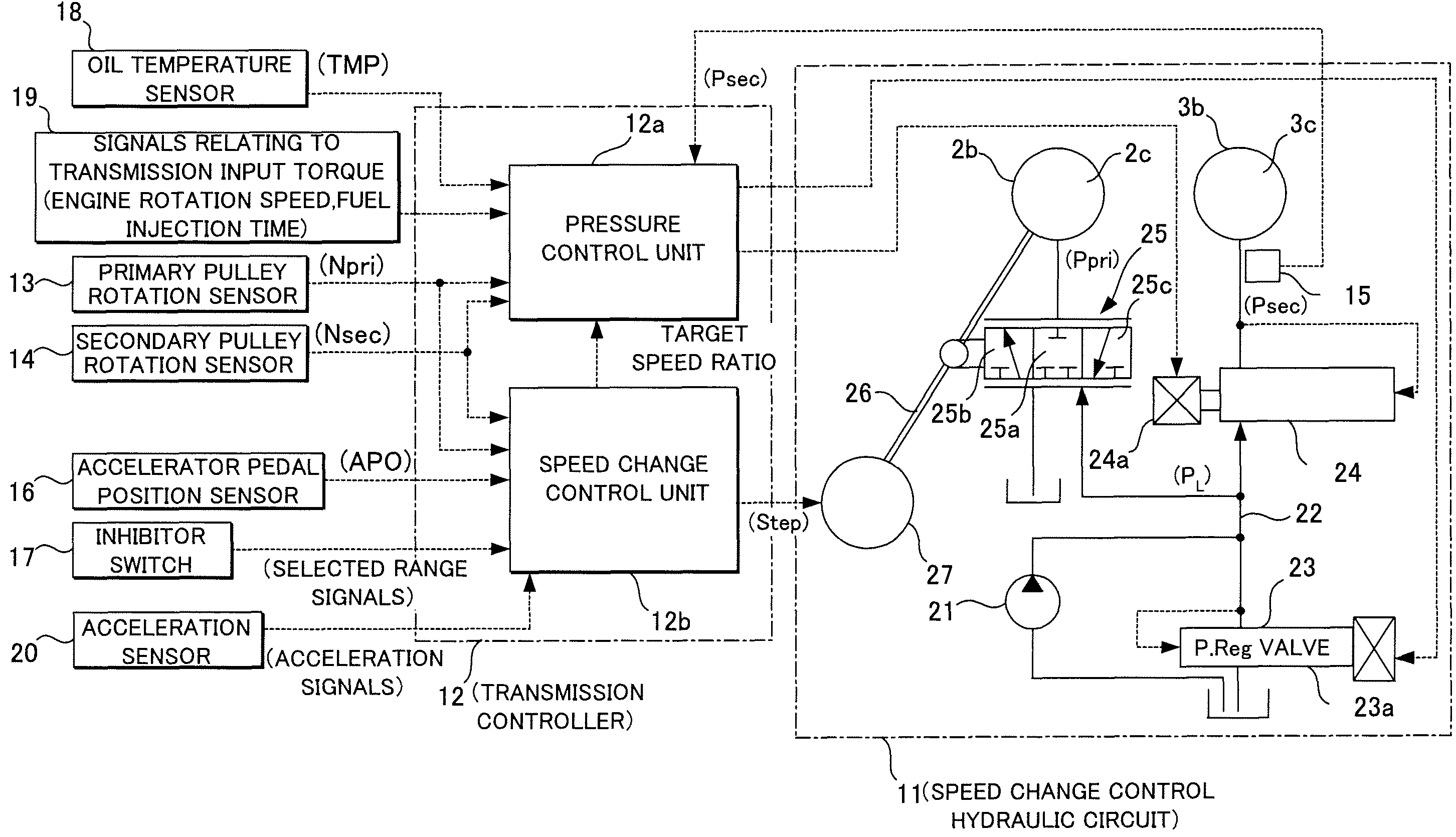
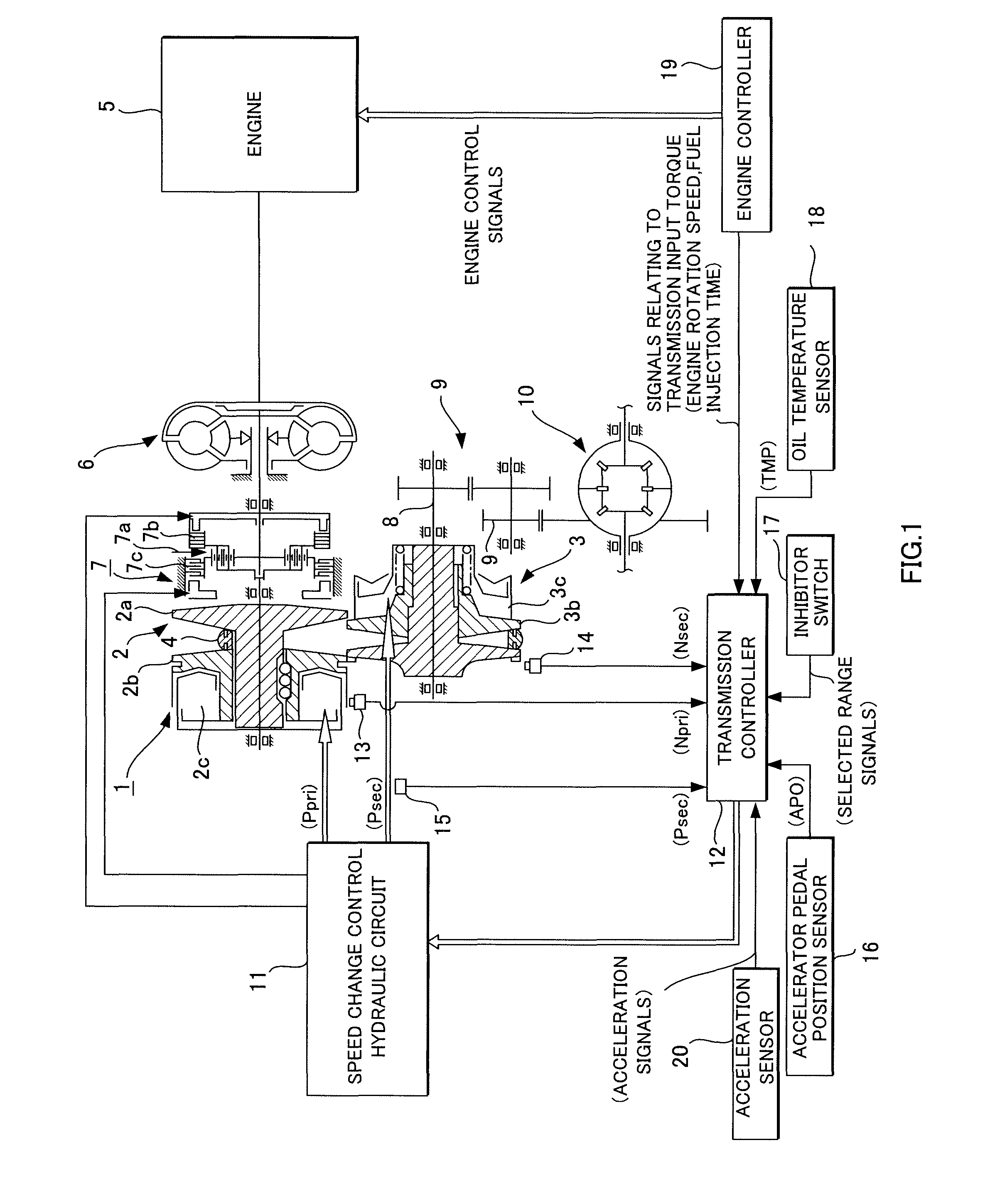
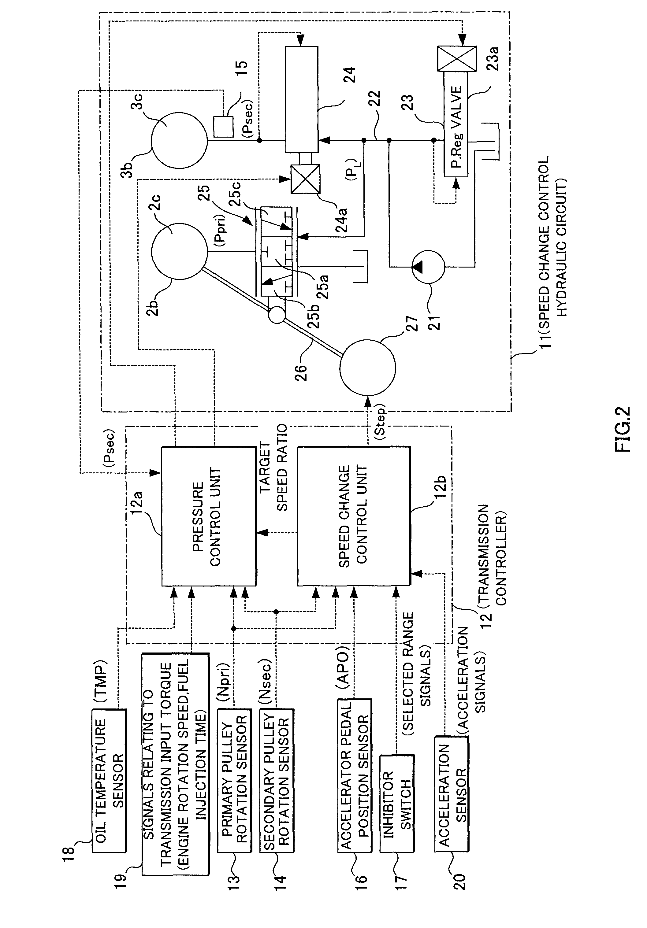
[0019]An embodiment of this invention will be described in detail below on the basis of the drawings. FIG. 1 shows an outline of a V-belt continuously variable transmission 1. The V-belt continuously variable transmission 1 comprises a primary pulley 2 and a secondary pulley 3 arranged such that the V-grooves of the two are aligned, and a V-belt 4 which is looped around the V-grooves of the pulleys 2, 3. An engine 5 is disposed coaxial with the primary pulley 2, and a torque converter 6 comprising a lockup clutch and a forward-reverse switching mechanism 7 are provided between the engine 5 and primary pulley 2 in succession from the engine 5 side.

[0020]The forward-reverse switching mechanism 7 comprises a double pinion planetary gear set 7a as a principal constitutional element, the sun gear thereof being joined to the engine 5 via the torque converter 6 and the carrier thereof being joined to the primary pulley 2. The forward-reverse switching mechanism 7 further comprises a forwar...


PUM


Abstract

During Low return control, in which a speed ratio determined by a contact radius of a V-belt (4) with a non-rotating primary pulley (2) and a non-rotating secondary pulley (3) is shifted toward lowest speed ratio while the vehicle is stationary, an estimated speed ratio (ic) is calculated on the basis of a secondary pulley pressure (Psec). When a start request is issued to the vehicle while Low return control is underway, a primary pulley pressure (Ppri) and the secondary pulley pressure (Psec) are controlled on the basis of the estimated speed ratio (ic).

Description

FIELD OF THE INVENTION[0001]This invention relates to a control device and a control method for a continuously variable transmission.BACKGROUND OF THE INVENTION[0002]In a vehicle installed with a continuously variable transmission, a belt is looped around a primary pulley and a secondary pulley, and a speed change is performed by varying a rotation radius of the belt relative to the primary pulley and the secondary pulley. As disclosed in JP63-074736A, when the vehicle brakes or decelerates, a speed ratio is returned to a lowest speed ratio in preparation for the next start following stopping, whereupon speed change control is performed to stop the vehicle. When the vehicle stops before the speed ratio returns to the lowest speed ratio during emergency braking or rapid deceleration, control is performed to return the speed ratio to the low side speed ratio after the next start so that the speed ratio is suitable for starting. During this type of control, however, the speed at which ...

Claims


Application Information

Patent Timeline
Patent Type & Authority Patents(United States)
IPC IPC(8): F16H61/00F16H61/664F16H63/00
CPCF16H59/70F16H61/66272F16H2061/6605Y10T477/624Y10T477/62427Y10T477/6242F16H2059/704F16H61/66F16H61/04
Inventor IWASA, HIROKIKODAMA, YOSHIHISA
Owner JATCO LTD
Why Eureka
Try Eureka