Method of manufacture of separation devices

a technology of separation device and manufacturing method, which is applied in the direction of filtration separation, moving filter element filter, separation process, etc., can solve the problems of clogging of particulates, conventional rigid filter pores that do not have a precise and well-defined cross-sectional shape or size, and the distribution of porosity of conventional rigid filter pores, etc., to prevent the fabrication of non-rounded features, the effect of rapid and economical means

Inactive Publication Date: 2010-09-07
THE UNITED STATES OF AMERICA AS REPRESETNED BY THE SEC OF THE AIR FORCE
View PDF3 Cites 10 Cited by
  • Summary
  • Abstract
  • Description
  • Claims
  • Application Information

AI Technical Summary

Benefits of technology

[0013]The term capillary has traditionally referred to a small round tube because they have been drawn from softened glass. The effect of surface tension on the soft glass wall of the tubing being drawn precludes the fabrication of non-rounded features. However, the term capillary as used in this application describes microscopic channels of any cross-sectional and / or axial shape made from any type of material. This term was chosen because a portion of the separation devices described in this invention function on the basis of varying degrees of capillary attraction between the capillary wall and a liquid contained therein. The capillaries in the majority of devices described in this application are imbedded in a solid structure.
[0014]This invention describes high- or low-pressure separation devices containing microscopic capillaries with precisely controlled dimensions in rigid or flexible materials having no interconnected porosity. These capillaries can have a variety of axial and cross-sectional shapes, which are useful for filtering particulates from a liquid or gaseous mixture as well as for separating particles on the basis of size. In addition, with the proper axial and cross-sectional shaping of these capillaries, and / or with a flexible adaptive capillary wall material, they are able to exclude particles or trap particles in the capillary and still allow the passage of gaseous or liquid flow through the filter. Finally, the entrance or inner surface of the microscopic capillaries in the separation devices described below can also, be chemically or physically tailored to admit or deny access to liquids and entrained particulates on the basis of wettability as well as chemical, physical, electrical or magnetic selectivity. This provides a rapid and economical means to separate a liquid mixture, separate liquids from gases in both single and two phase systems, and allow the passage of a gas through a separation device while excluding a liquid.

Problems solved by technology

However, these conventional rigid filters possess a distribution of porosity.
The pores in conventional rigid filters do not have a precise and well-defined cross-sectional shape or size.
In addition, they are subject to clogging by particulates.
This type of structure does not have much mechanical strength and therefore is not very useful at high pressure.
In addition, this type of structure, as with rigid filters, cannot guarantee an exact pore size, but rather provides a distribution of pore sizes around some average value.
This distribution of pore sizes does not allow for a precise threshold for particulate exclusion on the basis of size.
Finally, conventional microscopic screening is limited in mesh size and mesh shape, the position and arrangement of the individual mesh openings as well as the types of materials that can be employed.

Method used


Image

  • Method of manufacture of separation devices
  • Method of manufacture of separation devices
  • Method of manufacture of separation devices

Examples


Embodiment Construction

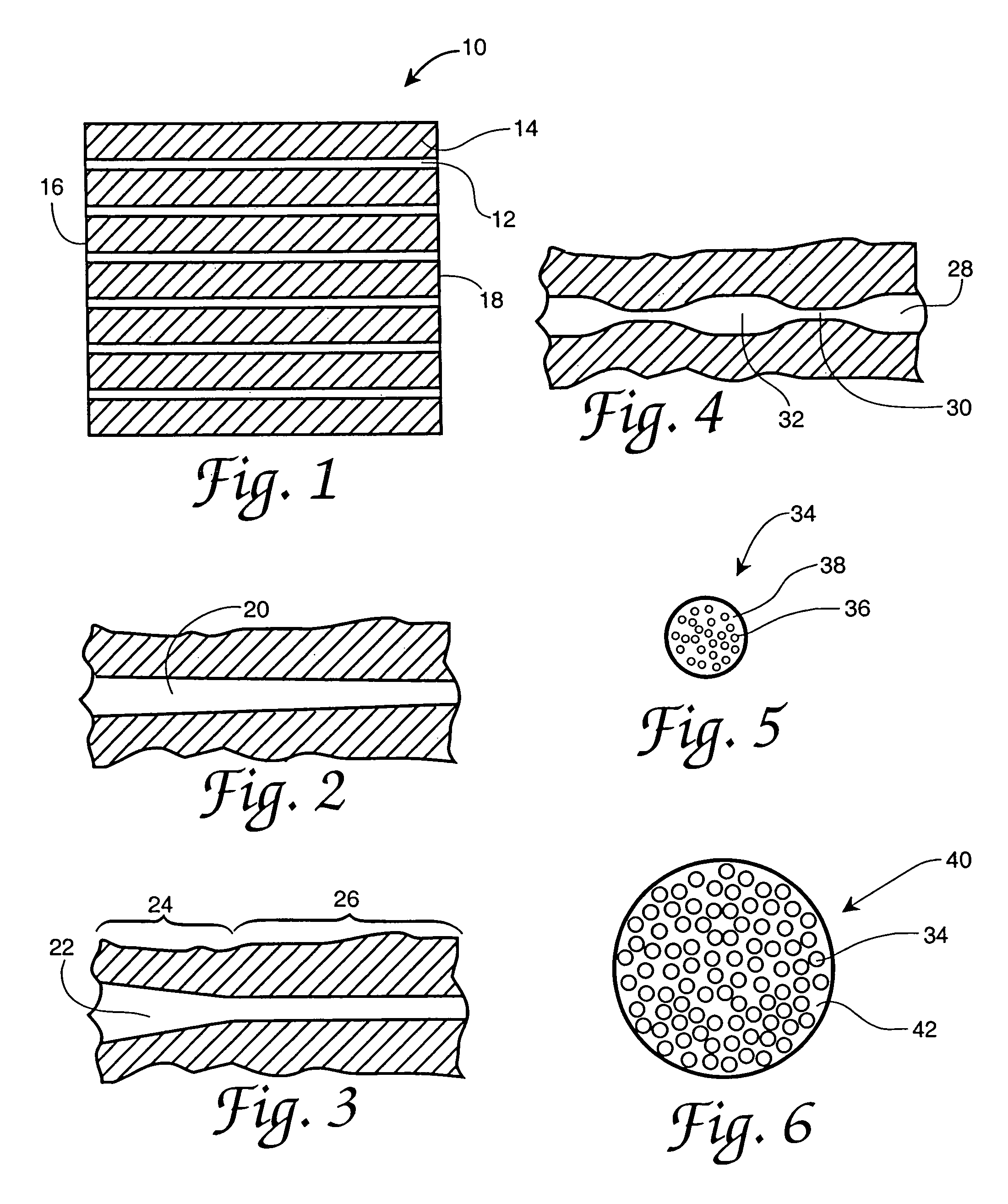
[0029]Referring now to the drawings, FIG. 1 illustrates a separation device 10 comprising a plurality of capillaries 12 embedded in a support material 14 and having an entrance face 16 and an outlet face 18. Device 10 is fabricated employing microtube technology, as disclosed by Hoffman, U.S. Pat. No. 5,011,566, issued Apr. 30, 1991. Briefly, this technology comprises placing a coating on a sacrificial fiber or fibers and then removing the fibers. The inner dimensions and contours of the capillaries will perfectly match the dimensions and contours of the fiber surfaces from which they were formed. In the separation devices of the present invention, capillary 12 can have any cross-section, including round, square, triangular, lobed, rectangular, polygonal and the like. For convenience, the material used to form capillary 12 will be referred to as “fiber”. The fiber can have any dimensions needed for the application as long as at least one cross-sectional dimension is in the range of ...


PUM

PropertyMeasurementUnit
thicknessaaaaaaaaaa
thicknessaaaaaaaaaa
thicknessaaaaaaaaaa

Abstract

Provided are methods for fabricating fluid separation devices with precisely-sized, shaped microscopic capillaries that can separate one immiscible fluid from another on the basis of different separation characteristics. In particular, the method comprises the steps of fabricating a first set of capillaries having a first separation characteristic and a second set of capillaries having a second separation characteristic, incorporating one end of all of the capillaries into an inlet face, incorporating the second end of the first set of capillaries into a first outlet face, and incorporating the second end of the second set of capillaries into a second outlet face. Preferably, the first set of capillaries is hydrophillic and the second set of capillaries is hydrophobic.

Description

CROSS REFERENCE TO RELATED APPLICATION[0001]This is a divisional application of application Ser. No. 10 / 435,004, filed May 9, 2003 now abandoned, which claims priority of the filing date of Provisional Application Ser. No. 60 / 379,991, filed May 13, 2002.RIGHTS OF THE GOVERNMENT[0002]The invention described herein may be manufactured and used by or for the Government of the United States for all governmental purposes without the payment of any royalty.BACKGROUND OF THE INVENTION[0003]The present invention relates to the manufacture or fabrication of separation devices. In one aspect, these devices include filters with precisely-sized and shaped microscopic capillaries. In another aspect, these devices include screens with precisely-sized and shaped microscopic mesh size, as well as adaptive and tailorable particulate filtration mediums based on elastic / plastic deformation. In a further aspect, these devices include fluid separation devices with precisely-sized, shaped microscopic cap...

Claims


Application Information

Patent Timeline
Patent Type & Authority Patents(United States)
IPC IPC(8): B01D11/00B01D39/00
CPCB01D17/0202B01D17/10
Inventor WAPNER, PHILLIP G.HOFFMAN, WESLEY P.
Owner THE UNITED STATES OF AMERICA AS REPRESETNED BY THE SEC OF THE AIR FORCE
Why Eureka
Try Eureka