Method of forming parylene film

a parylene film and film technology, applied in the direction of liquid surface applicators, coatings, metal material coating processes, etc., can solve the problems of significant increase in fabrication costs, costly replacement fees, and damage to throttle valves, so as to prevent the discontinuation of fabrication caused by vacuum release

Active Publication Date: 2014-11-18
IND TECH RES INST
View PDF20 Cites 3 Cited by
  • Summary
  • Abstract
  • Description
  • Claims
  • Application Information

AI Technical Summary

Benefits of technology

[0013]Accordingly, in the invention, the buffer chamber is disposed in front of the evaporator; thus when refilling the parylene material during the fabrication, the refilling step can be performed by turning off the valve between the buffer chamber and the evaporator and delivering the parylene material to the buffer chamber. Moreover, the stopping of the CVD apparatus or the discontinuation of the fabrication caused by releasing vacuum can be prevented by refilling the parylene material with the foregoing method. Consequently, the parylene film can be fabricated continuously.

Problems solved by technology

However, the evaporated parylene gas easily deposits in an environment under 150° C. Accordingly, the parylene film is usually formed on the throttle valves, and this leads to damages of the throttle valves and requires costly replacement fees.
In addition, when powdered raw material is replaced with aqueous raw material to overcome the above problem, the fabrication cost significantly increases as the price of aqueous raw material is about 100 times of that of powdered raw material.
Nevertheless, in the process of forming the parylene film with this CVD apparatus, when the parylene material has been consumed, the apparatus needs to be stopped to refill the parylene powder and cool the temperature therefore to room temperature, thereby failing to fabricate continuously.

Method used


Image

  • Method of forming parylene film
  • Method of forming parylene film
  • Method of forming parylene film

Examples


Embodiment Construction

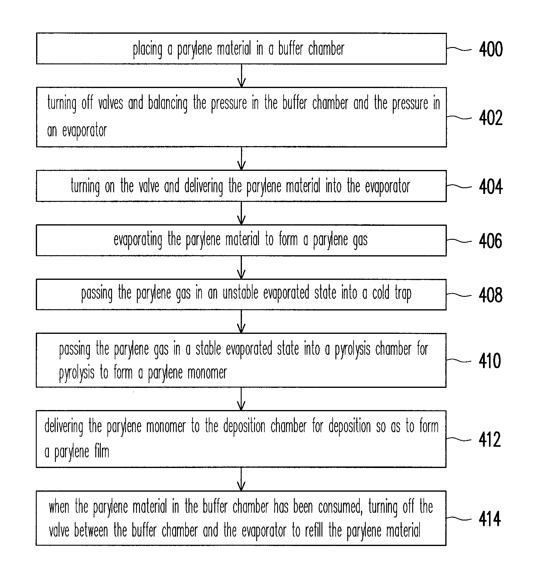
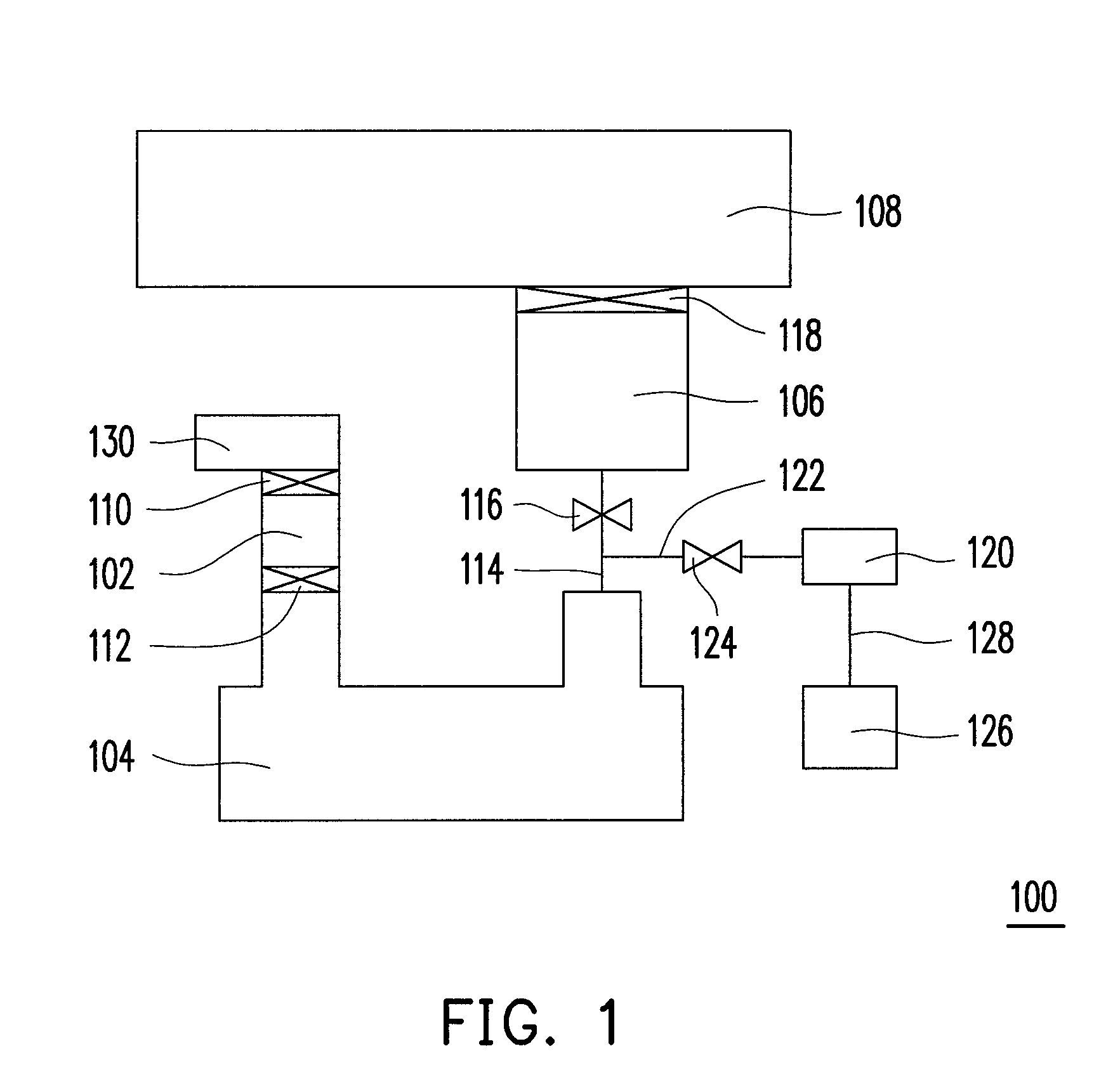
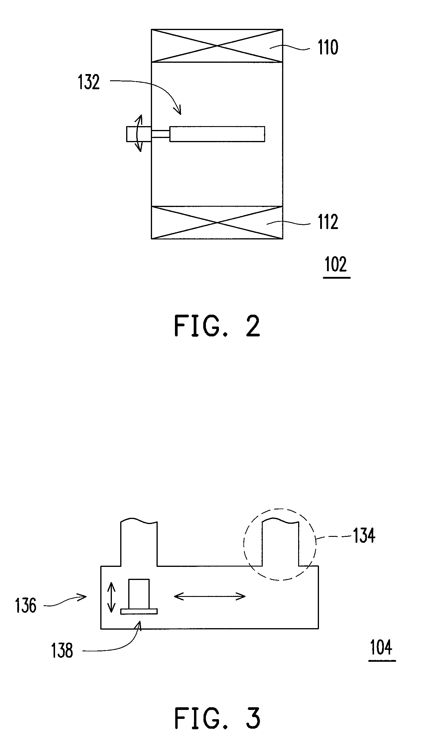
[0020]FIG. 1 is a schematic view of a chemical vapor deposition (CVD) apparatus according to one embodiment of the invention. Referring to FIG. 1, a CVD apparatus 100 includes a buffer chamber 102, an evaporator 104, a pyrolysis chamber 106, and a deposition chamber 108. The buffer chamber 102 has a first valve 110 and a second valve 112. The first valve 110 is, for example, a gate valve configured to connect or disconnect the buffer chamber 102 and the external environment. The second valve 112 is, for example, a gate valve configured to connect or disconnect the buffer chamber 102 and the evaporator 104. The evaporator 104 is connected with the second valve 112. The evaporator 104 evaporates the material to form a reactive gas adopted in the CVD process. The pyrolysis chamber 106 is connected with the evaporator 104 through a first pipe 114, where the first pipe 114 has a third valve 116. The pyrolysis chamber 106 is configured to perform a pyrolysis to the reactive gas in the CVD...


PUM

PropertyMeasurementUnit
evaporating temperatureaaaaaaaaaa
pressureaaaaaaaaaa
water resistanceaaaaaaaaaa

Abstract

A method for forming a parylene film is provided, which includes following steps. Providing a chemical vapor deposition apparatus including a buffer chamber having first and second valves and a rotative carrying apparatus, an evaporator connected with the second valve, a pyrolysis chamber connected with the evaporator, and a deposition chamber connected with the pyrolysis chamber. Placing a parylene material in the rotative carrying apparatus of the buffer chamber through the first valve. Turning off the first and second valves and balancing a pressure in the buffer chamber and a pressure in the evaporator. Turning on the second valve and delivering the parylene material into the evaporator. Evaporating the parylene material in the evaporator to form a parylene gas. Pyrolyzing the parylene gas in the pyrolysis chamber to form a parylene monomer. Delivering the parylene monomer to the deposition chamber for deposition so as to form a parylene film.

Description

CROSS-REFERENCE TO RELATED APPLICATION[0001]This application claims the priority benefit of Taiwan application serial no. 98143702, filed on Dec. 18, 2009. The entirety of the above-mentioned patent application is hereby incorporated by reference herein and made a part of this specification.BACKGROUND OF THE INVENTION[0002]1. Field of the Invention[0003]The invention relates to a deposition apparatus and a method of forming a film. More particularly, the invention relates to a chemical vapor deposition apparatus and a method of forming a parylene film.[0004]2. Description of Related Art[0005]Parylene film has superior water resistance and oxygen resistance, high transparency and insulation, and capability in preventing rust, corrosion, and efflorescence. Thus, parylene film is usually adopted as the gas barrier layer on the surface of the flexible plastic substrate in current flexible displays.[0006]In conventional fabrication, a parylene film is generally formed by a chemical vapor...

Claims


Application Information

Patent Timeline
Patent Type & Authority Patents(United States)
IPC IPC(8): B05D1/00C23C16/452C23C16/26C23C16/44
CPCB05D1/60C23C16/452C23C16/54C23C16/45561C23C16/4485
Inventor CHANG, CHUN-HAOZHUANG, CHUAN-SHENG
Owner IND TECH RES INST
Why Eureka
Try Eureka