High torque electric motor/flywheel

a high-torque, electric motor technology, applied in the direction of mechanical energy handling, magnetic circuit rotating parts, magnetic circuit shape/form/construction, etc., can solve the problems of increasing the cost, size and weight of the motor, rotor to vibrate or otherwise become unstable, rotor to deflect or cant along the axis, etc., to achieve the effect of improving rotational balance and facilitating removal

Inactive Publication Date: 2010-09-07
ATTARD MICHAEL T
View PDF19 Cites 3 Cited by
  • Summary
  • Abstract
  • Description
  • Claims
  • Application Information

AI Technical Summary

Benefits of technology

[0010]It is an advantage of the present invention to provide an electric motor having a rotor frame comprised of two opposed frusto-conically shaped supports.
[0011]It is another advantage of the present invention to provide a rotor including a plurality of removable blocks containing the rotor's magnetic elements. The blocks including quick connect / disconnect electrical connections to facilitate removal.
[0012]It is still another advantage of the present invention to provide an electric motor having its rotor and stator in a generally ball-shaped configuration to improve rotational balance and to present the largest magnetic surface area over a particular diameter.
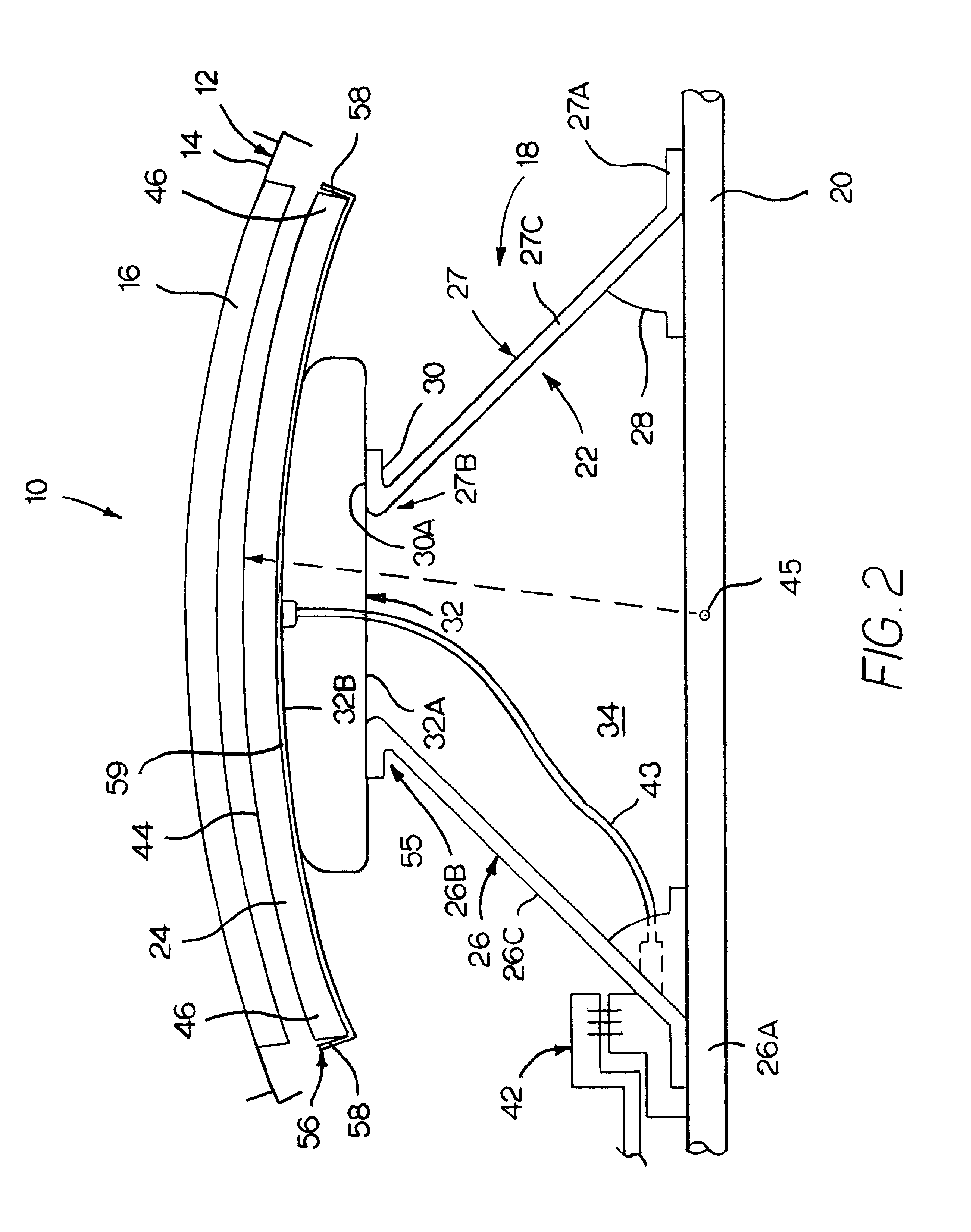
[0013]It is yet another advantage of the present invention to provide an electric motor having a rotatable output shaft including a rotor assembly and a stator. The rotor includes a support member fixed to the output shaft. The support member is formed from a pair of spaced frusto-conical-shaped walls, each wall is mounted to the output shaft at a first end and tapers radially away from the output shaft and toward the other wall, terminating at a second end. The rotor also includes first magnetic means or elements mounted to the support member. The stator rotatably receives the rotor and includes second magnetic means or elements which are arranged around the stator effective to cause the rotor to rotate and turn the output shaft.
[0014]It is still yet another advantage of the present invention to provide a high-torque electric motor comprising a rotor assembly mounted to a central output shaft and a stator having a housing which defines an internal rotor-receiving cavity. The rotor assembly comprising a two cone-shaped support member, each having a hub fixedly mounted to the output shaft. Elongated annular walls taper away from the hubs at an angle and terminates at an outer end, wherein the support members are mounted to the output shaft such that the annular walls taper toward each other. The rotor assembly also includes a plurality of electromagnets mounted to the support members at their outer ends and are spaced evenly around the output shaft. The stator including a plurality of permanent magnets that are axially spaced evenly about the rotor-receiving cavity.
[0015]It is still yet another advantage of the present invention to provide an electric motor that rotates an output shaft, comprising: a first rotor support shell having a cone-shaped wall which tapers from a first narrow end to a first wide end, wherein the first rotor support shell is fixed to the output shaft at the first narrow end; a second rotor support shell having a cone-shaped wall which tapers from a second narrow end to a second wide end, wherein the second rotor support shell is fixed to the output shaft at the second narrow end, wherein the shells are mounted to the output shaft such that the shells taper toward each other; a toroid-shaped mounting base which is fixedly mounted to the first and second wide ends; a plurality of support arms which extend from opposite sides of the mounting base, the support arms running generally parallel to the output shaft, the arms are axially spaced evenly around each side of the mounting base, wherein an outer peripheral surface of the mounting base and an outer peripheral surface of the arms cooperate to form a ball-shaped magnet-mounting surface; a plurality of wedge-shaped electromagnets, the electromagnets are mounted to the mounting base and the arms at the magnet-mounting surface, the outer periphery of each of the electromagnets cooperatively define a ball-shaped outer surface.

Problems solved by technology

While these systems will produce greater amounts of torque, they increase the motor's cost, size and weight.
Increasing the motor's rotational speed, while increasing the motor's power output, generally causes the rotor to vibrate or otherwise become unstable.
One example of this instability is that the rotor will deflect or cant along its axis.
This deflection and vibration limits how fast a particular motor may be run.
One cause of this undesirable deflection at higher rotational speeds is that the support members / torque arms of conventional rotors typically project orthogonally from the rotor shaft and do not have adequate support along the rotational axis (along the rotor shaft).

Method used


Image

  • High torque electric motor/flywheel
  • High torque electric motor/flywheel
  • High torque electric motor/flywheel

Examples


Embodiment Construction

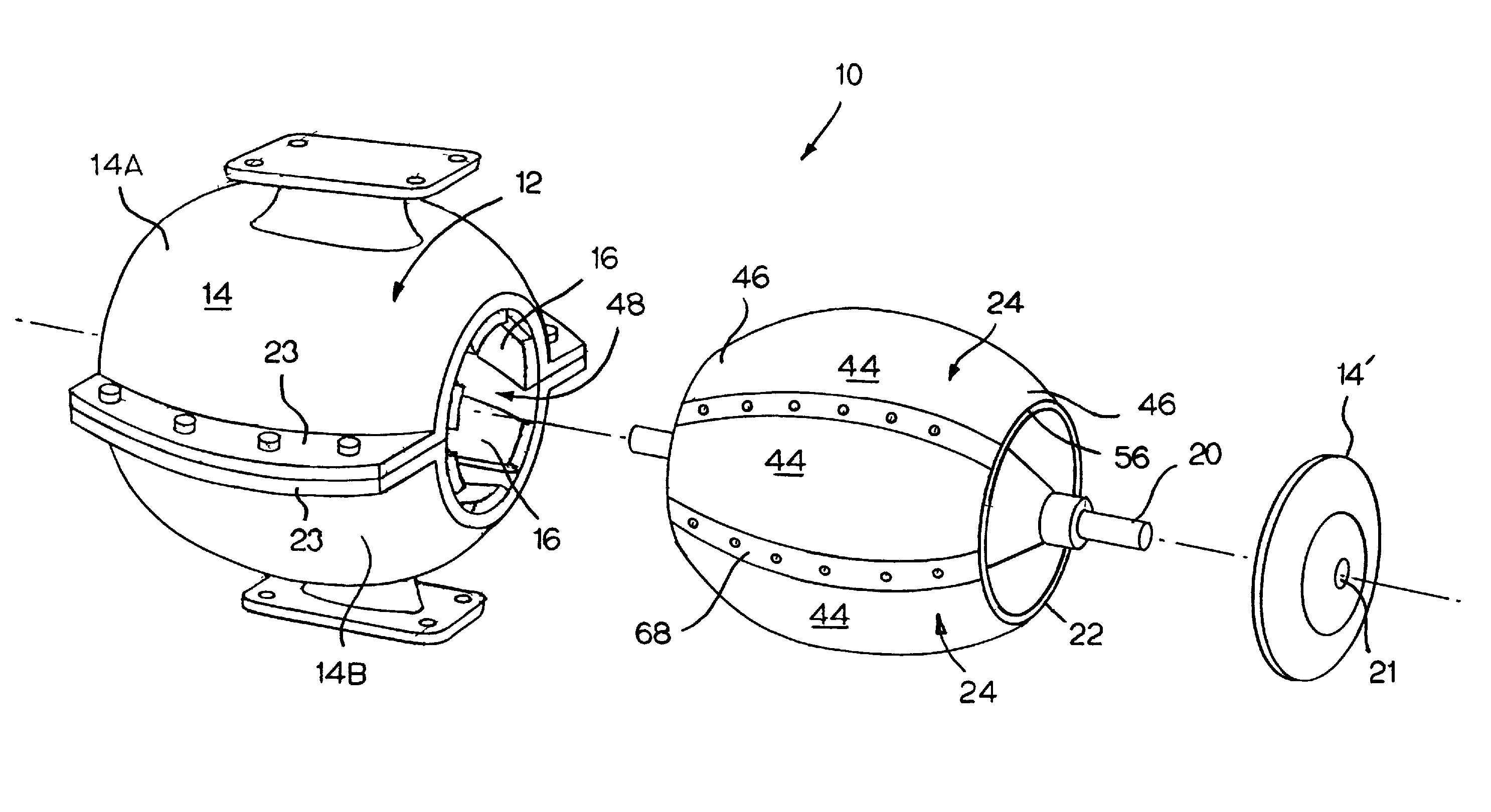
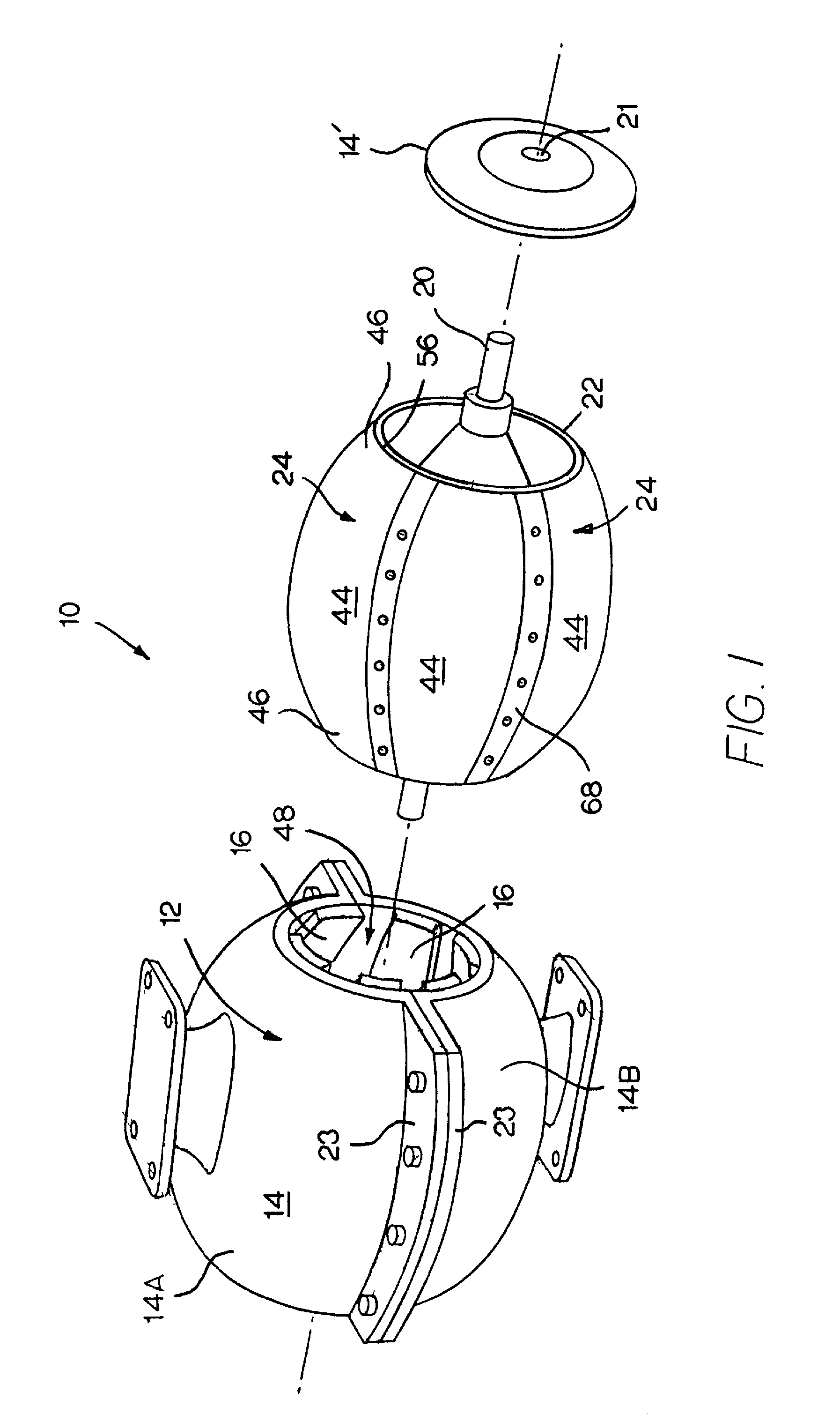
[0028]Referring now to FIG. 1, an improved electric motor 10 is shown including a stator 12 having a housing 14 which contain a magnetic elements or means 16, such as a plurality of permanent magnets. Motor 10 also includes a rotor assembly 18 which is fixedly mounted to a central output shaft 20. Shaft 20 is free to rotate on bearing means 21 that are mounted to stator housing 14. In the preferred embodiment, stator housing 14 is formed in two separable sections 14A, 14B which are joined along side flanges 23 by conventional means, such as mechanical fasteners. In one embodiment, a stator cover plate 14′ encloses the rotor assembly 18 when mounted within the generally cylindrical stator cavity. In this embodiment, this plate 14′ includes the bearing means 21 that engage the output shaft 20.

[0029]Rotor assembly 18 includes a support member 22 that is fixed to the output shaft 20 and magnetic elements or means 24 peripherally mounted to support member 22.

[0030]Support member 22 inclu...


PUM


Abstract

A high-torque electric motor having a rotor supported by an elongated torque arm comprising a pair of frustoconical-shaped support members. The rotor has a spherical-shaped outer surface and a complementarily shaped stator cavity. The spherical magnetic elements and the conical support members cooperate to brace the rotor against deflection along its rotational axis.

Description

FIELD OF THE INVENTION[0001]This invention relates to electric motors. More particularly, to electric motors having an elongated rotor torque arm mounted to the output shaft to increase the torque applied to the output shaft.BACKGROUND OF THE INVENTION[0002]An electric motor's power is proportional to its torque and rotational speed. Increasing one or both of these properties increases the motor's power (i.e., its horsepower).[0003]An electric motor has two basic components: a stator and a rotor. At least one of these components includes magnets, whose magnetic fields cause the rotor to move relative to the stator, usually by rotating about a central shaft.[0004]The stator is the stationary electrical component. It typically includes a group of individual permanent magnets or electro-magnets arranged in a way to form a hollow, generally cylindrical shell with one pole of each magnet facing toward the center of the group.[0005]The rotor is the rotating electrical component and typica...

Claims


Application Information

Patent Timeline
Patent Type & Authority Patents(United States)
IPC IPC(8): H02K37/00H02K23/60H02K21/12H02K1/22
CPCH02K1/30H02K21/28
Inventor ATTARD, MICHAEL T.
Owner ATTARD MICHAEL T
Why Eureka
Try Eureka