AM (amplitude modulation) demodulation system for RFID reader device

a demodulation system and amplitude modulation technology, applied in amplitude demodulation, electric devices, chain drives, etc., can solve the problems of further limitation and inability to achieve effective demodulation, and achieve the effect of facilitating original square wave filtering

Active Publication Date: 2010-09-07
DATAMARS
View PDF5 Cites 7 Cited by
  • Summary
  • Abstract
  • Description
  • Claims
  • Application Information

AI Technical Summary

Benefits of technology

[0026]The solution idea of the present invention is to provide the RFID reader device with at least a couple of cheap and simple demodulators for demodulating the AM wave in a couple of respective first and second outputs, substantially corresponding to opposite Amplitude side of the AM wave, and an enforcing block for subtracting the first and second outputs and obtaining a resulting output, having a frequency grater with respect to the first and second outputs, from which frequency it is easier to filter the original square wave.
[0035]Advantageously, the AM demodulation system according to the present invention is based on a simple and cheap configuration of electronic components, for example including only a couple of demodulators respectively comprising a diode, a capacitor and a resistor.
[0036]Advantageously, the AM demodulation system retrieves an enforced demodulated output from which it is easier to filter the square wave corresponding to data modulated by a RFID tag through an AM wave 20.
[0038]Advantageously, the enforced demodulated output is easier to be filtered because the residual carrier frequency is two times greater than the current carrier frequency transmitted by the RFID reader device. Moreover, subtracting the two demodulated output, any noise may be canceled.

Problems solved by technology

Even if the AM demodulation system based on the demodulator like the one referred by numeral 6 are very cheap and simple, they are limited for the fact that they do not allow an effective demodulation of the AM wave 20, especially if it is disturbed.
More particularly, this problem is further limiting if the frequency of the square wave 3a to be decoded is not much lower than the frequency of the carrier wave 50.

Method used


Image

  • AM (amplitude modulation) demodulation system for RFID reader device
  • AM (amplitude modulation) demodulation system for RFID reader device
  • AM (amplitude modulation) demodulation system for RFID reader device

Examples


Embodiment Construction

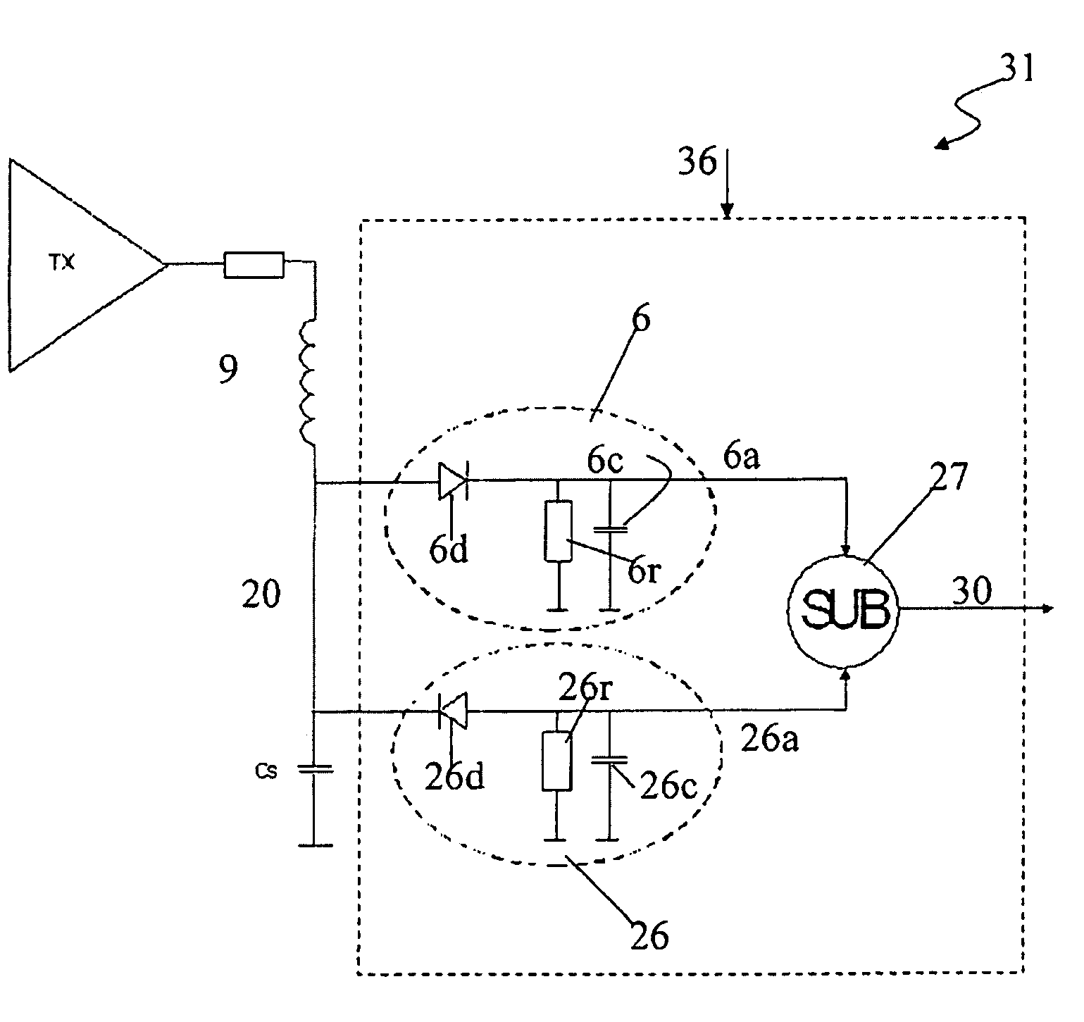
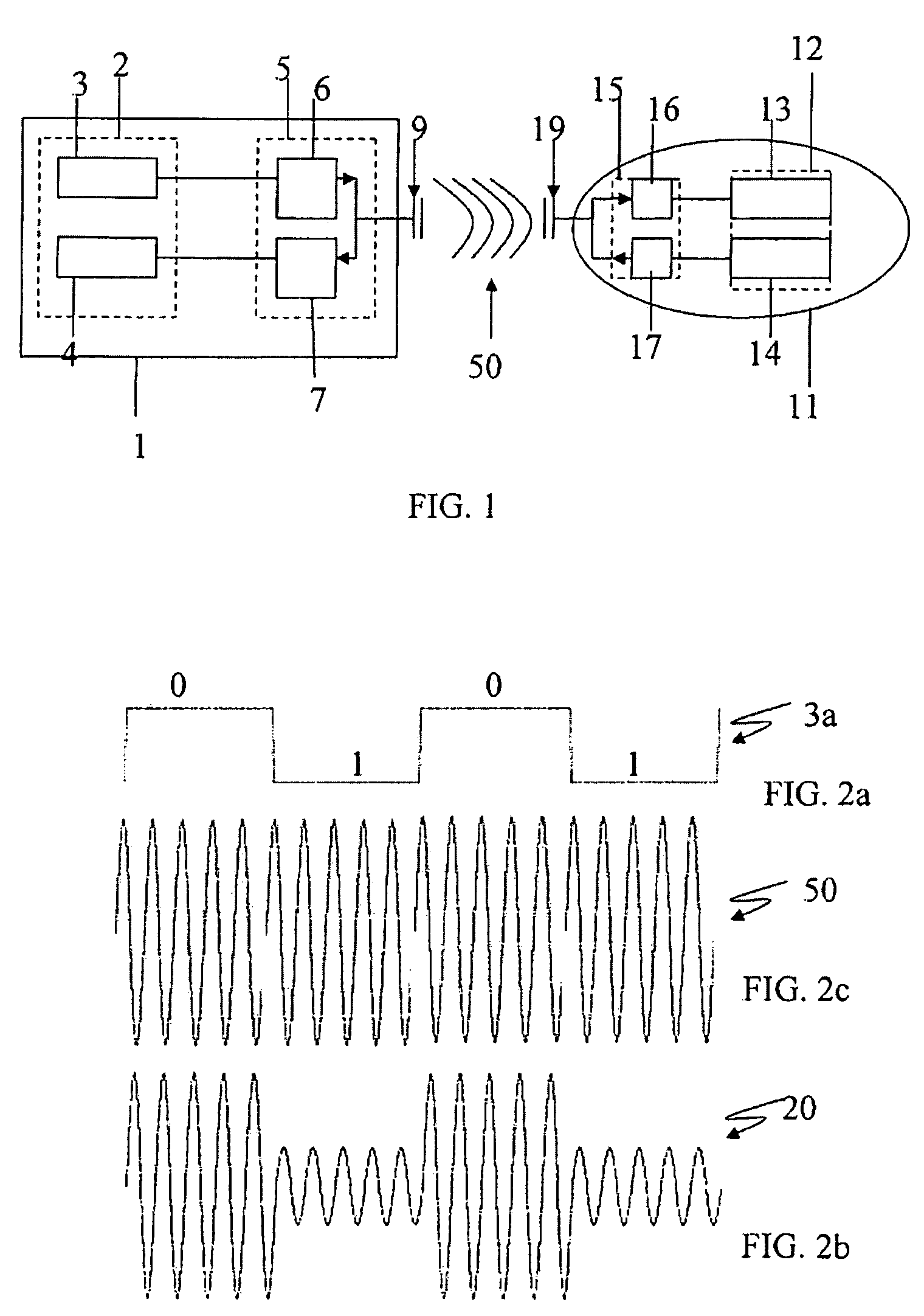
[0055]With reference to the annexed drawings and with numeral reference 36 is schematically represented an AM demodulation system for an RFID (Radio Frequency Identification) reader device 31 providing that a modulated RF (Radio Frequency) signal 20 , transmitted by an RFID tag, is demodulated into a demodulated output 30.

[0056]More particularly, the RFID reader device 31 comprises a magnetic loop antenna 9 to emit a magnetic field. When an RFID tag is absorbed in the magnetic field produced by the RFID reader device 31, it activates and modulates an RF modulated signal 20, for transmitting an ID number or more complex data stored in a non-volatile memory unit of the tag. The magnetic loop antenna 9 operates at low frequency, i.e. 134.2 Khz.

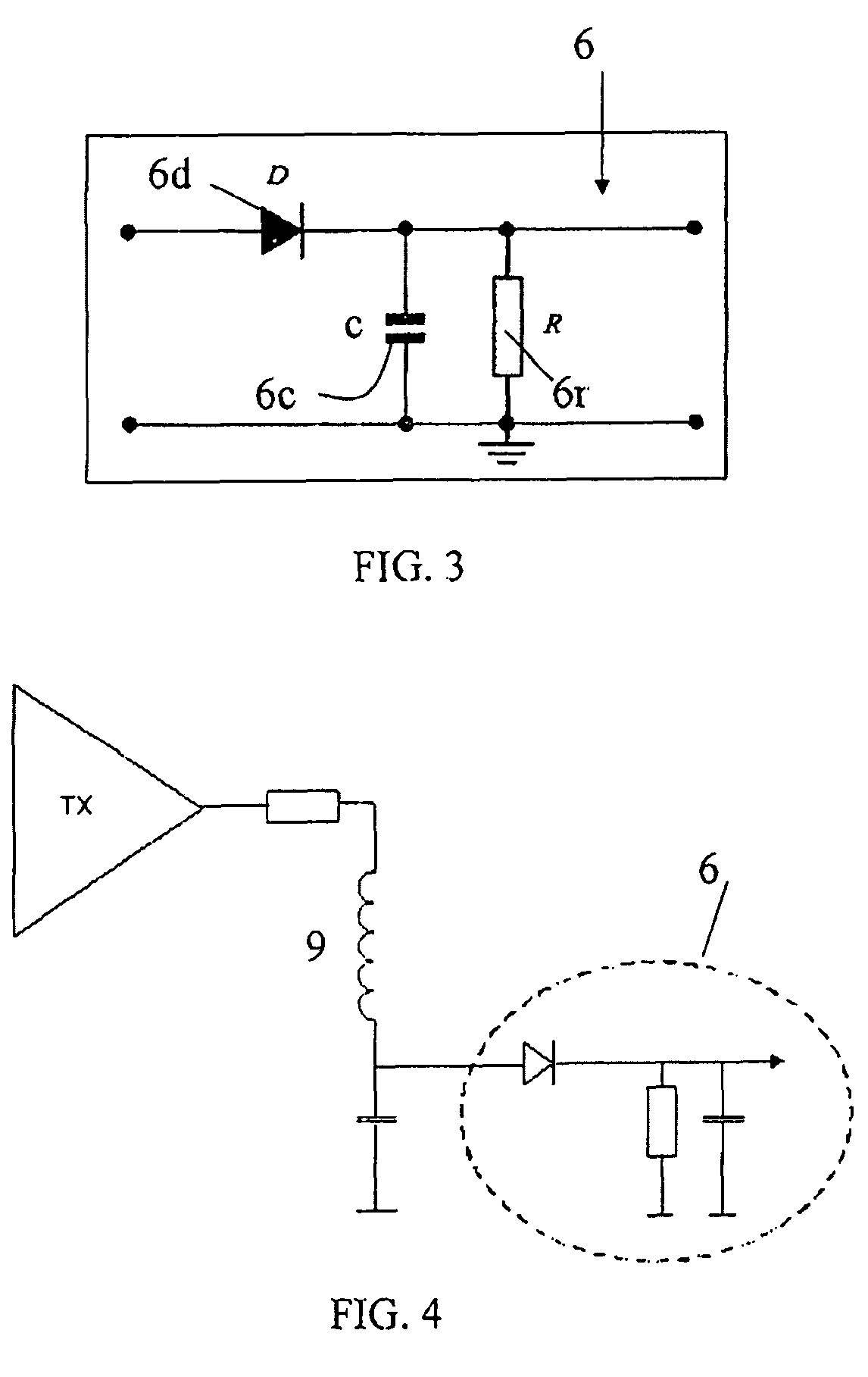
[0057]The RFID reader device 31 comprises an internal circuitry, including the AM demodulation system 36. The RFID tag is not provided with an internal power supply but uses the minute electrical current, induced in the antenna of the tag by the ...


PUM


Abstract

AM (Amplitude Modulation) demodulation system (36) for an RFID reader device (31), of the type comprising a demodulator (6) for receiving from a RFID tag (11) an AM (Amplitude Modulation) wave (20) having a predetermined frequency (f) and for retrieving, from the AM wave (20), a demodulated output (6a) associated to predetermined positive or negative Amplitudes of said AM wave (20). The AM demodulation system comprises at least a second demodulator (26) for receiving the AM wave (20) and retrieving a second demodulated output (26a) associated to Amplitudes opposite to the predetermined positive or negative Amplitudes and a block (27) having, in input, the demodulated output (6a) and the second demodulated output (26a) and returning, in output, an enforced demodulated output (30) with a frequency (f1) greater than the predetermined frequency (f).

Description

FILED OF APPLICATION[0001]The present invention relates to an AM (Amplitude Modulation) demodulation system for an RFID (Radio Frequency Identification) reader device of the type comprising a demodulator for receiving, from an RFID tag, an AM wave having a predetermined frequency and for retrieving, from the AM wave, a demodulated output associated to predetermined positive or negative Amplitudes of the AM wave.[0002]The present application also relates to a method for AM demodulation for an RFID reader device, comprising the steps of:[0003]receiving from an RFID tag an AM wave having a predetermined frequency;[0004]retrieving, from the AM wave, a demodulated output associated to predetermined positive or negative Amplitudes of the AM wave.PRIOR ART[0005]As it is well known, an AM (Amplitude Modulation) demodulation system for an RFID (Radio Frequency Identification) reader device provides to demodulate an RF (Radio Frequency) signal modulated by an RFID tag, in order to retrieve a ...

Claims


Application Information

Patent Timeline
Patent Type & Authority Patents(United States)
IPC IPC(8): H03D1/00H03D1/08H03D1/10
CPCH03J1/10
Inventor ARRIGO, AYDIN
Owner DATAMARS
Why Eureka
Try Eureka