
Speaker

a technology of speaker and electrode, applied in the field of speaker, can solve the problems of affecting the electrostatic capacity between the electrodes may be affected by friction, and the electrostatic capacity between the electrodes is affected and varied, and achieves the effect of accurate detection

Active Publication Date: 2010-09-07
CHEMTRON RES
View PDF8 Cites 0 Cited by
  • Summary
  • Abstract
  • Description
  • Claims
  • Application Information

AI Technical Summary

Benefits of technology

"The present invention provides a speaker with an electrostatic capacity detection function. This is achieved by accurately detecting the electrostatic capacity formed between the electrodes and the center pole using a stepped portion in the side circumferential face of the center pole. The electrostatic capacity detection is important for accurately detecting the position of the voice coil bobbin in the speaker. The invention also provides a method for accurately detecting the electrostatic capacity using a subtracter and a nonmagnetic electric conductor film. The invention further includes a design for the stepped portion in the center pole to facilitate the accurate detection of the electrostatic capacity. Overall, the invention provides a speaker with improved accuracy in detecting the electrostatic capacity."

Problems solved by technology

Therefore, the electrostatic capacity is affected and varied by noise such as a few amount of an electromagnetic wave or static electricity.
However, the electrostatic capacity between the electrodes is affected and varied by an exciting current flowing through the voice coil bobbin.
Further, the electrostatic capacity between the electrodes may be affected by friction accompanied with mechanical phenomena such as the vibration of components which are incorporated in the speaker, static electricity caused by various electromagnetic phenomena in the inside and the outside of the speaker, electromagnetic waves which are outputted by electronic equipment installed around the speaker, or the like.
Thus, in the above-mentioned references, since the electrostatic capacity varies as described above, the electrostatic capacity formed between the electrodes is unable to be accurately detected.

Method used


Image

  • Speaker
  • Speaker
  • Speaker

Examples


Embodiment Construction

[0027]A speaker in accordance with an embodiment will be described in detail below with reference to the accompanying drawings.

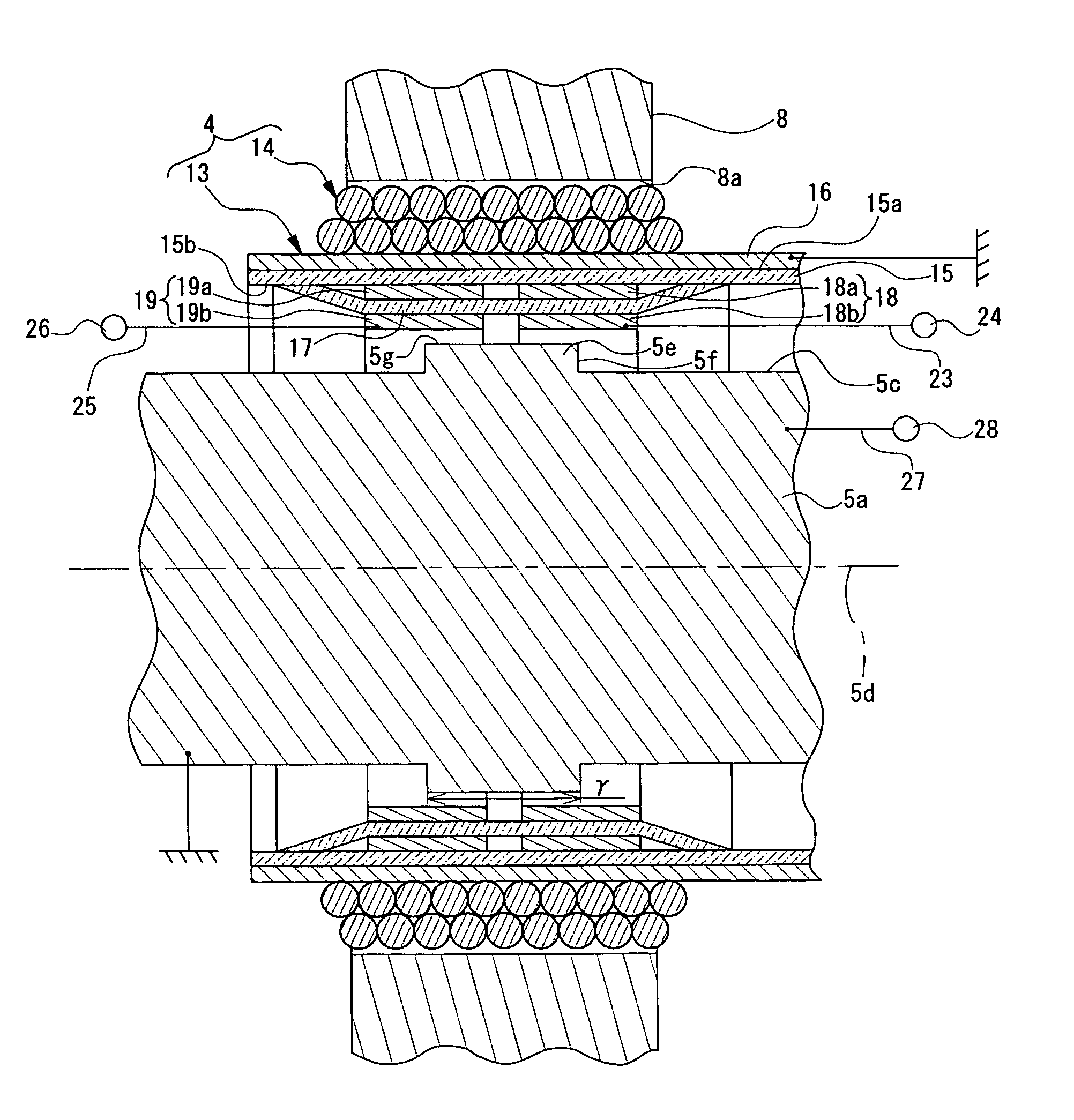
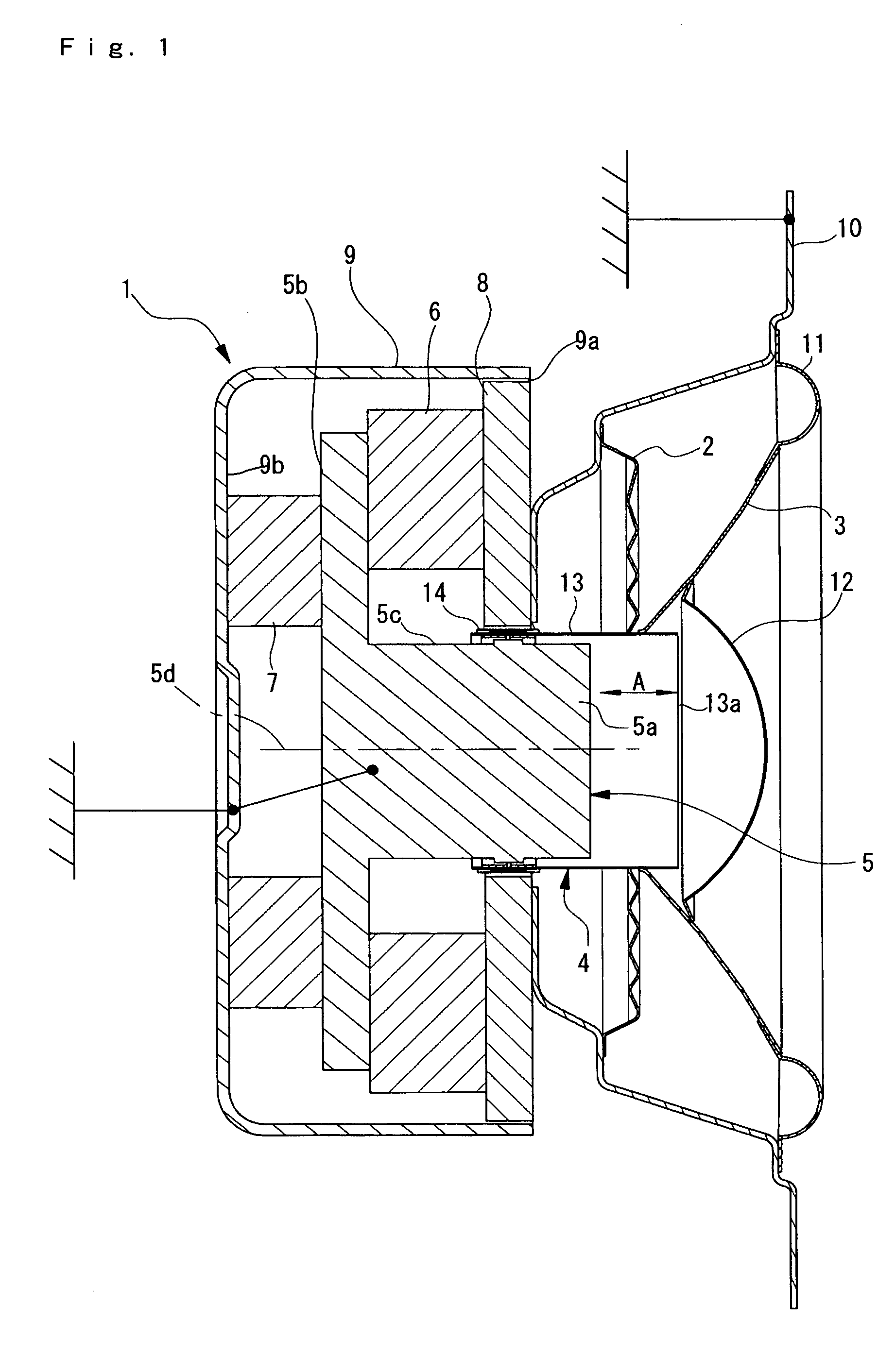
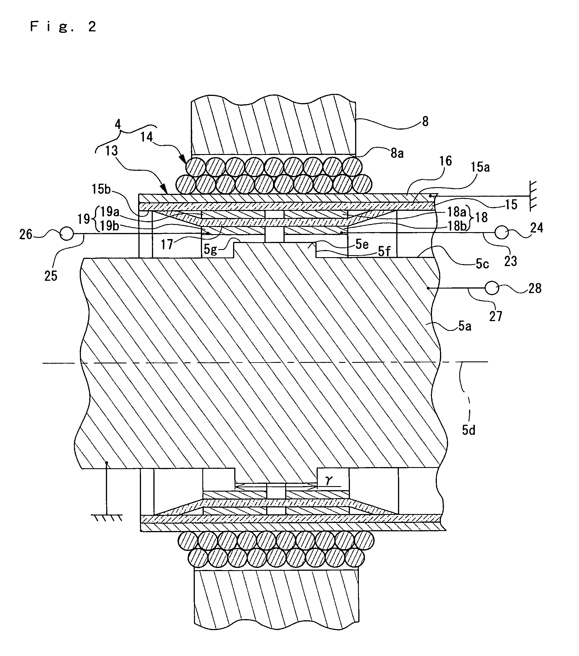
[0028]A speaker is shown in FIGS. 1 through 8. In a speaker 1 in accordance with an embodiment, two first electrodes 18 (18a, 18b) and two second electrodes 19 (19a, 19b) for detecting an electrostatic capacity are disposed with a predetermined space in-between on an inner peripheral face 15b of a pipe body 15 along an axis 5d direction of a center pole 5. Further, a stepped portion 5e is formed in the side circumferential face 5c with which, when a voice coil bobbin 4 is operated, a first facing area between one of the electrodes and the side circumferential face 5c of the center pole 5 is increased and a second facing area between the other of the electrodes and the side circumferential face 5c is decreased by the increased amount of the first facing area. In addition, a subtracter 31, in which subtraction between a first electrical signal obtained from on...


PUM


Abstract

A speaker may include a center pole, a voice coil bobbin having a nonmetallic pipe body, and a first and a second electrodes which are provided on an inner peripheral face of the pipe body for detecting an electrostatic capacity. The first and the second electrodes are disposed so as to be separated from each other with a predetermined space along an axial direction of the center pole. Further, a stepped portion may be formed in the side circumferential face of the center pole such that, when the voice coil bobbin is operated, a first facing area of the first electrode to the side circumferential face defined by the stepped portion of the center pole increases while a second facing area of the second electrode to the side circumferential face defined by the stepped portion of the center pole decreases by a same amount as an increased amount of the first facing area.

Description

CROSS REFERENCE TO RELATED APPLICATION[0001]The present invention claims priority under 35 U.S.C. §119 to Japanese Application No. 2005-282181 filed Sep. 28, 2005, which is incorporated herein by reference.FIELD OF THE INVENTION[0002]An embodiment of the present invention may relate to a speaker. More specifically, an embodiment of the present invention may relate to a speaker which detects an electrostatic capacity formed between a voice coil bobbin and a center poles to control the operation of a diaphragm on the basis of the detection result.BACKGROUND OF THE INVENTION[0003]In some audio speakers, a Motion Feed Back (MFB) circuit is included to improve the sound quality of the speaker. The MFB circuit detects the operating state of a diaphragm which vibrates through an electrical signal conveying audio information (hereinafter referred to as an “audio signal”) that is inputted into the speaker. The MFB circuit feedback-controls the diaphragm based on the detection result. In this...

Claims


Application Information

Patent Timeline
Patent Type & Authority Patents(United States)
IPC IPC(8): H04R25/00
CPCH04R9/06
Inventor USHIKOSHI, AKINORITAKAHASHI, SHINSUKEYOKOYAMA, KENJI
Owner CHEMTRON RES
Learn More