
Power management system using a multi-master multi-slave bus and multi-function point-of-load regulators

a power management system and multi-master technology, applied in the direction of electric variable regulation, process and machine control, instruments, etc., can solve the problems of mismatch between the respective output voltages of the pol regulators, the power supply design has become a much more critical and difficult task, and the failure to meet the requirements of the power supply, etc., to achieve the effect of maintaining compatibility

Active Publication Date: 2010-09-07
INTERSIL INC
View PDF39 Cites 48 Cited by
  • Summary
  • Abstract
  • Description
  • Claims
  • Application Information

AI Technical Summary

Benefits of technology

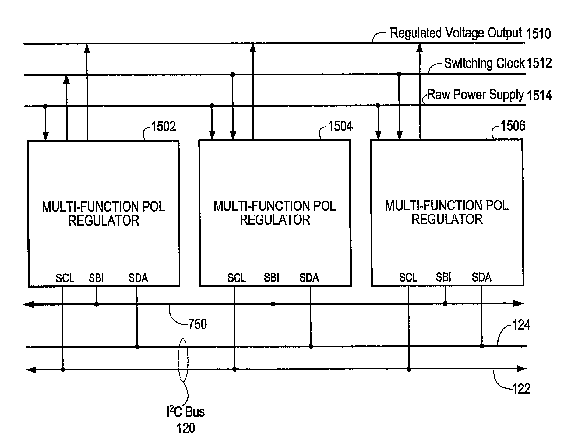
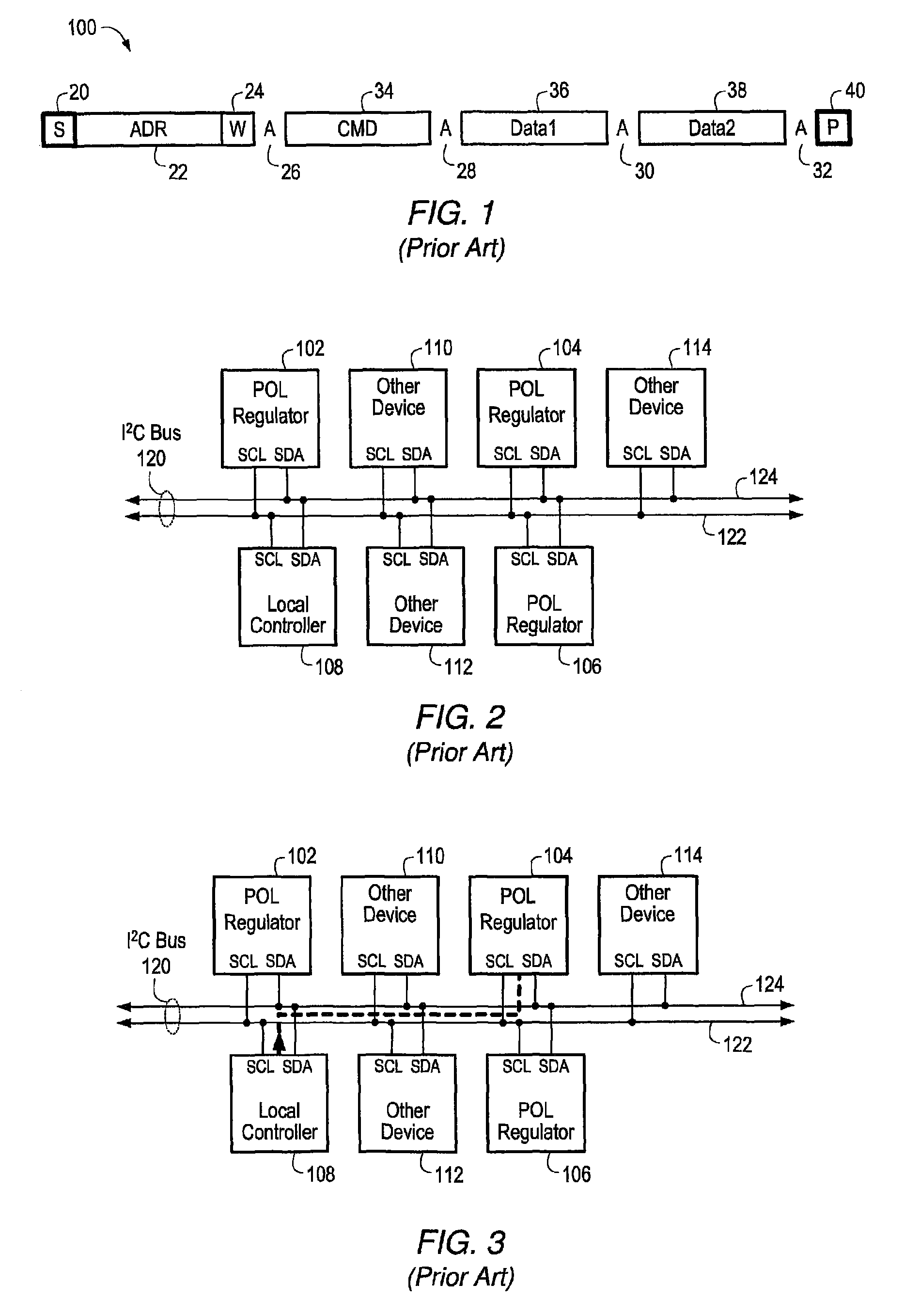
"The patent describes a power management system that allows multiple power management functions to be performed using a shared digital bus interface. The system uses a multi-master multi-slave interface, such as I2C or SMBus, to transfer information between POL regulators. Each POL regulator is configured to monitor the bus transactions of other POL regulators and make decisions autonomously based on its own state and the information it receives from other regulators. The POL regulators may perform a variety of power management functions, including voltage tracking, current balancing, and phase spreading, without needing a local controller or additional components. The system is designed to be highly flexible and adaptable to different power management requirements."

Problems solved by technology

Power supply design has become a much more critical and difficult task than it was a few years ago.
With the rising complexity and robustness requirements of many systems, the ability to monitor and control the power distribution sub-system has become increasingly more critical.
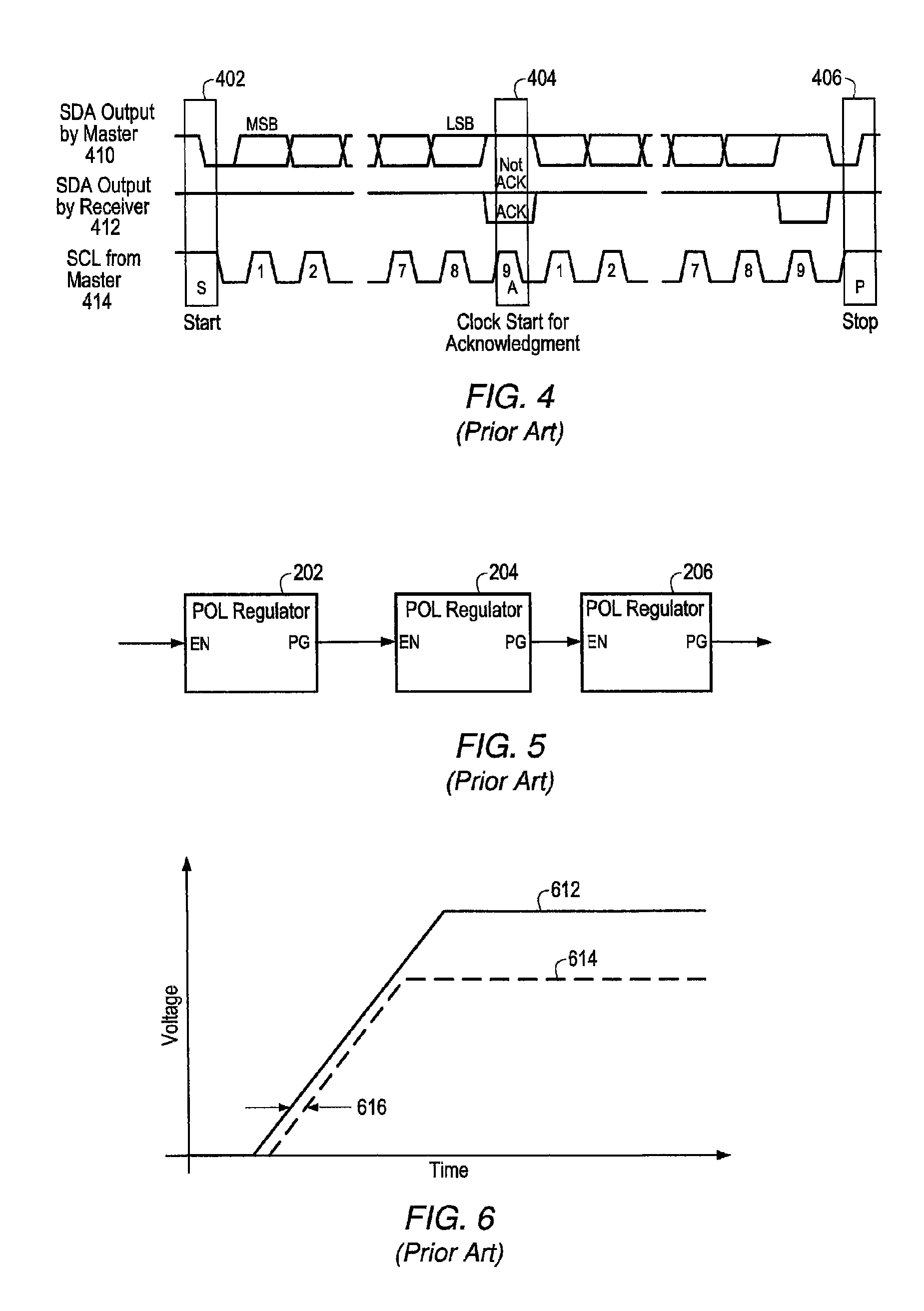
However, mismatch between the oscillators configured within different POL regulators may result in the turn-on and turn-off ramps of the different POL regulators changing at different rates, thereby introducing a mismatch between the respective output voltages of the POL regulators.

Method used


Image

  • Power management system using a multi-master multi-slave bus and multi-function point-of-load regulators
  • Power management system using a multi-master multi-slave bus and multi-function point-of-load regulators
  • Power management system using a multi-master multi-slave bus and multi-function point-of-load regulators

Examples


Embodiment Construction

[0048]As used herein, a device coupled to a bus that is “uniquely identified by an address” refers to a device identified by an address or addresses that are not shared with any other device that is also coupled to the bus. That is, the address that identifies a specified device does not identify any other device. However, more than one address may uniquely identify a single device. For example, a device may be uniquely identified by address ‘34ef45’ and also by address ‘34ef44’, but neither ‘34ef45’ nor ‘34ef44’ may identify any other device. Furthermore, “targeting an address” during a bus operation refers to initiating the bus operation addressing a device uniquely identified by the address. For example, if a first device coupled to the bus has a specified first address that uniquely identifies the first device, and a second device initiates a write operation “targeting the specified first address”, then the address information transmitted by the first device as part of initiatin...


PUM


Abstract

A power management system may comprise two or more POL regulators configured to transmit and receive data over a shared bus according to either a proprietary or a common bus protocol. Each POL regulator may be identified by a unique address that is part of an address group, and may be configured via pin strapping to be able to perform a variety of power management functions. Any one of the POL regulators within the address group may become a bus master and transmit information to the shared bus by addressing itself. The other POL regulators in the address group may monitor the shared bus for events, and may respond to the transmitted information according to their address, their configuration, and the transmitted information. The response may include the POL regulators performing one or more power management functions, including adjusting their respective output voltages. The POL regulators may respond to each event according to the requirements corresponding to the event, thereby performing the necessary tasks to enable power management functions without the need for interconnecting analog signal lines and without being explicitly controlled.

Description

CONTINUATION-IN-PART[0001]This application is a continuation-in-part of U.S. patent application Ser. No. 11 / 198,698 filed Aug. 5, 2005 now U.S. Pat. No. 7,653,757 and titled “Method for Using a Multi-Master Multi-Slave Bus for Power Management”, whose inventors are Kenneth W, Fernald, James W. Templeton, and John A. Wishneusky, and which claims benefit of priority of U.S. provisional application Ser. No. 60 / 599,369 filed Aug. 6, 2004 and titled “Method For Using A Multi-Master Multi-Slave Bus For Power Management”.[0002]This application is additionally a continuation-in-part of U.S. patent application Ser. No. 10 / 820,976 filed Apr. 8, 2004 now U.S. Pat. No. 7,506,179 and titled “Method And Apparatus For Improved DC Power Delivery, Management And Configuration”, whose inventor is James W. Templeton, and which claims benefit of priority of U.S. provisional application Ser. No. 60 / 462,414 filed Apr. 11, 2003 and titled “Method And Apparatus For Improved DC Power Delivery, Management An...

Claims


Application Information

Patent Timeline
Patent Type & Authority Patents(United States)
IPC IPC(8): G06F3/00G05F1/40
CPCG06F1/26H02M3/1584
Inventor FERNALD, KENNETH W.TEMPLETON, JAMES W.WISHNEUSKY, JOHN A.
Owner INTERSIL INC
Learn More