Tension locking tool

a technology of locking tool and handle, which is applied in the field of hand tools, can solve the problems that the locking pliers are generally not able to be utilized as a regular the locking capability of the handle members is not always intact, and the conventional types of pliers are generally not able to be utilized as a normal set of conventional pliers, so as to achieve convenient use.

Active Publication Date: 2010-09-14
GOOD SPORTSMAN MARKETING LLC
View PDF53 Cites 5 Cited by
  • Summary
  • Abstract
  • Description
  • Claims
  • Application Information

AI Technical Summary

Benefits of technology

[0028]One convenient method of locking the pliers units to the tension member is to have the second tension location attach to the tension member by a first engagement member and a second engagement member positioned on opposing longitudinal sides of the tension member. This allows for a quick release tension member system and the first and second engagement members can have a plurality of teeth that are facing one another, and the first and second engaging members are offset in the transverse direction such that where the plurality of teeth of the first and second engagement members engage correspondingly sized and spaced members of the tension member when in the locked orientation and when the second plier unit is in an unlocked orientation, the first and second engagement members disengage from the teeth of the tension member so as to allow the second plier unit to reposition in the transverse direction.
[0029]A tension quick release assembly can be provided where the length of the tension member is adjusted by repositioning a pillow block in the longitudinal direction of the first handle member and first and second engaging members are provided to disengage from a threaded rod so as to allow the pillow block member to freely reposition in a longitudinal direction. Engagement extensions are connected to engagement members positioned between the pillow block providing engagement thereof where a slanted surface maintains engagement of the engaging members to the threaded rod when the pillow block is in tension by the tension member. The first and second engaging members can have a biasing member to bias the first and second engagement members laterally apart from one another away from the threaded rod to allow the pillow block to freely slide along the threaded rod. This arrangement allows for convenient use of the tool as a regular plier and can be applied to a locking tool by engaging the pillow block to the threaded rod. In this form a spring member biases the pillow block longitudinally rearwardly.
[0030]In one form a main gear is attached to a threaded rod gear so as to provide a mechanical advantage upon rotating the threaded rod for rotation thereof.

Problems solved by technology

Of course one issue with this arrangement is that the locking pliers are generally not capable of being utilized as a regular set of conventional pliers, for example to quickly clamp upon a variety of sizes of materials without necessarily adjusting the orientation of the compression cross-link member.
However, conventional types of pliers, as well as conventional non-locking multi-tools, generally do not have any sort of locking capability to remain intact upon a material when the handle members are no longer grasped.

Method used


Image

  • Tension locking tool
  • Tension locking tool
  • Tension locking tool

Examples


Embodiment Construction

[0088]This application incorporates by reference U.S. Provisional Serial Number 69 / 923,928, filed Apr. 17, 2007.

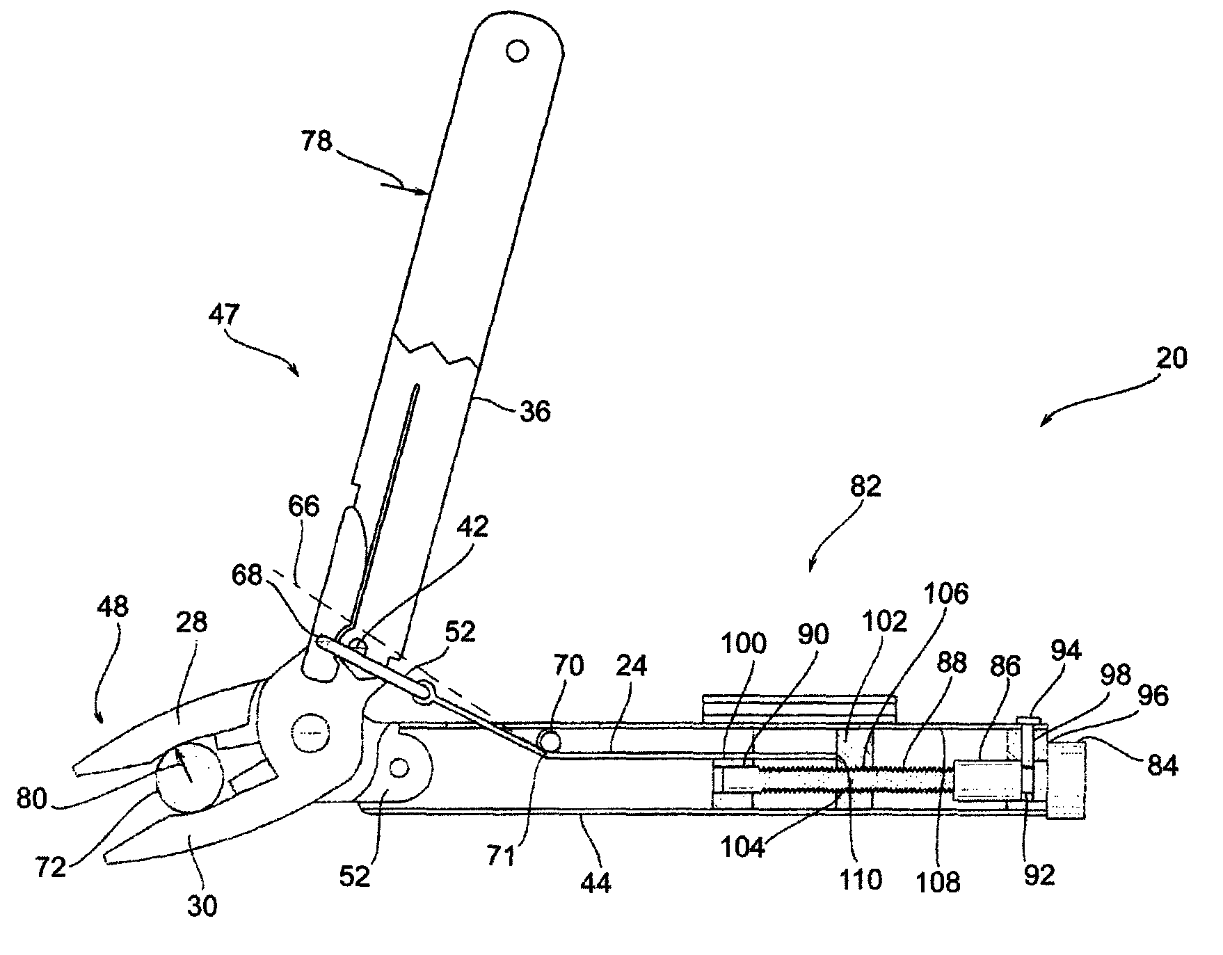
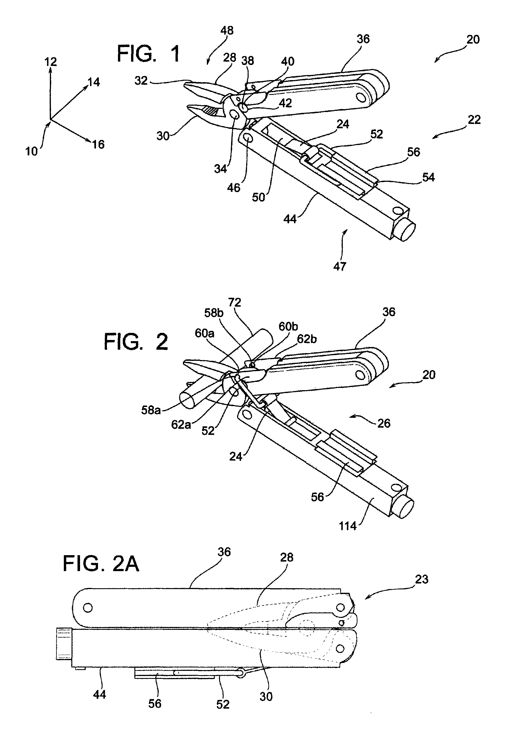
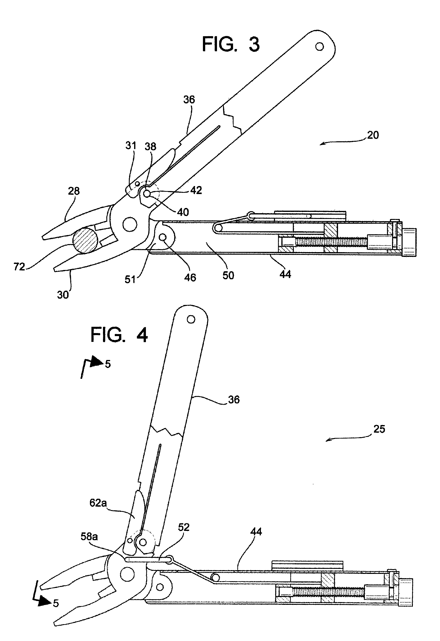
[0089]As shown in FIG. 1, there is a locking multitool 20. In general, the locking multitool 20 has the capability of providing a clinching-like locking of the jaw assembly 48 by utilization of a tension member 24 as shown in FIG. 2. By way of general background, locking pliers have been utilized in the prior art, such as traditional Vise-Grip™ pliers which have an intermediate interposed compression locking member utilized to exert an expanding force to lock such prior art jaw assemblies. As will be discussed in detail herein, a combination of the jaw assembly 48 and the handle members 36 and 44 operate in conjunction with a tension member 24 providing an operational tool for locking an object such as the material 72 in FIG. 2 whereby the jaw assembly 48 will remain locked upon the object without any external force upon the locking multitool 20.

[0090]The basic operating p...


PUM


Abstract

A hand tool having first and second plier units attached to one another where a jaw region is operatively configured to have a work piece to be placed therein and a handle region is configured to be used by the user of the tool to grasp the work piece. A tension member is provided to be positioned past a dead point axis so as to apply a clamping force upon the jaw member and the hand tool maintains a grip upon the work piece without continuous interaction with the user of the tool.

Description

RELATED APPLICATIONS[0001]This application claims priority benefit of U.S. Provisional Ser. No. 60,923,928, filed Apr. 17, 2007.BACKGROUND OF THE DISCLOSURE[0002]a) Field of the Disclosure[0003]This disclosure relates to the field of hand tools, specifically hand tools having a clamping portion similar to traditional pliers.[0004]b) Background Art[0005]Hand tools for gripping material and work pieces are commonly utilized devices which are generally known as pliers. Pliers have been formed in a variety of embodiments in the prior art but generally operate on the principle of having a central pivot member between two plier members. Some prior art pliers have the capability to lock the jaw portion of the pliers without constant interaction of the tool handler.[0006]Locking multi-tools using a member under compression such as that disclosed in U.S. Pat. No. 4,318,316 are also fairly common. Locking plier technology has even been applied to folding multi-tools, such as that disclosed in...

Claims


Application Information

Patent Timeline
Patent Type & Authority Patents(United States)
IPC IPC(8): B25B7/12
CPCB25B7/08B25B7/10B25B7/123B25B7/12B25B7/14B25B13/18B25B13/28
Inventor MATTSON, CHRISTOPHER ANDREWWINDER, BRIAN G.MACKAY, ALLEN BOYDJACOBSEN, JOSEPH O.HALVERSON, PETER A.FRAZER, SPENCER
Owner GOOD SPORTSMAN MARKETING LLC
Why Eureka
Try Eureka