
Engine brake apparatus

a technology of engine valves and brakes, which is applied in the direction of valve arrangements, machines/engines, non-mechanical valves, etc., can solve the problems of difficulty in adjusting timings and/or amount of engine valve lift, and achieve the effect of expanding the volume of the hydraulic circui

Active Publication Date: 2010-09-14
JACOBS VEHICLE SYST
View PDF7 Cites 4 Cited by
  • Summary
  • Abstract
  • Description
  • Claims
  • Application Information

AI Technical Summary

Benefits of technology

The system reduces transient loads on valve train elements, enabling more efficient engine braking and improved valve actuation control, optimizing engine performance across different operating conditions.

Problems solved by technology

The use of fixed profile cams, however, can make it difficult to adjust the timings and / or amounts of engine valve lift in order to optimize them for various engine operating conditions, such as different engine speeds.

Method used


Image

  • Engine brake apparatus
  • Engine brake apparatus
  • Engine brake apparatus

Examples


Embodiment Construction

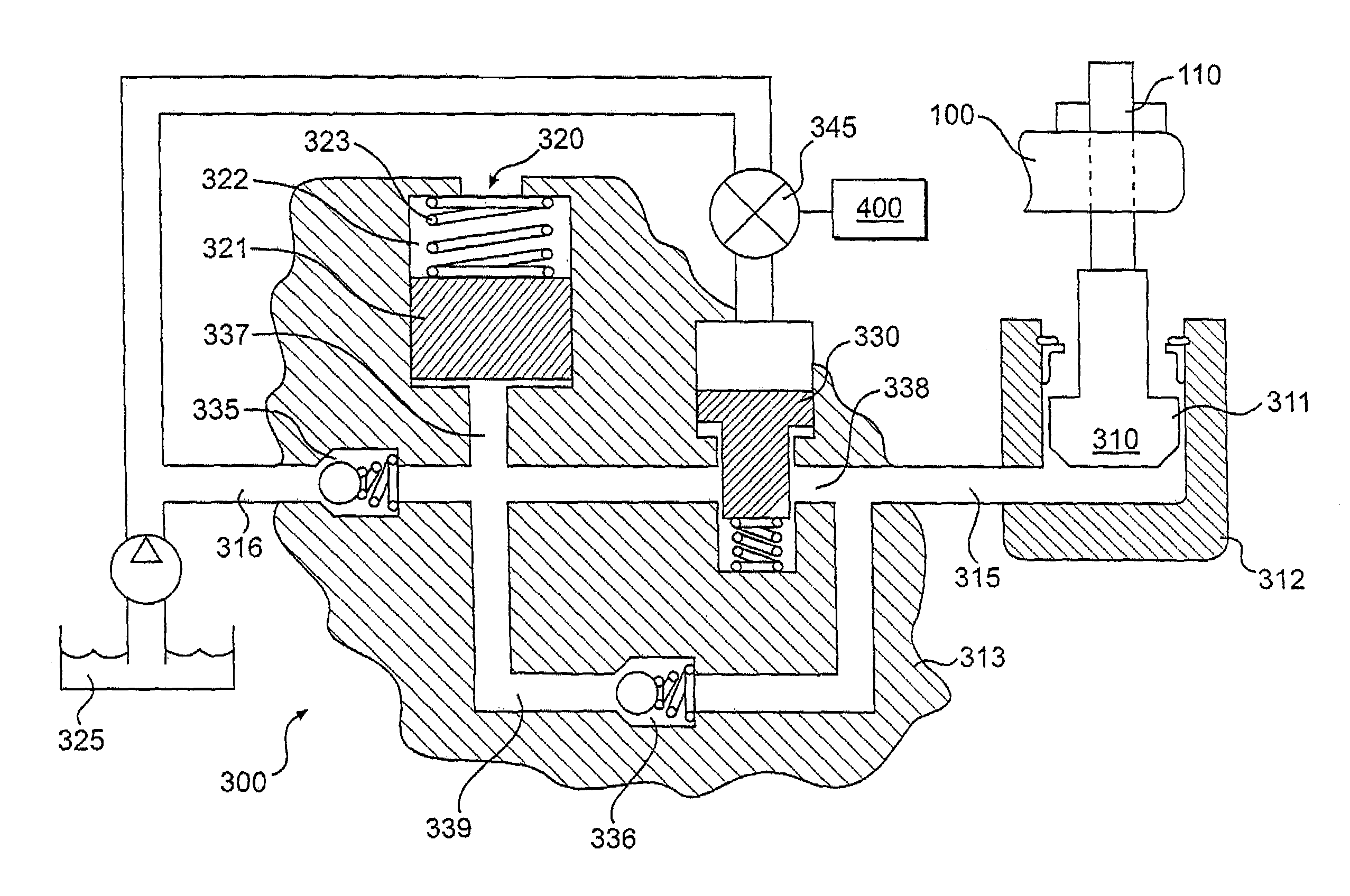
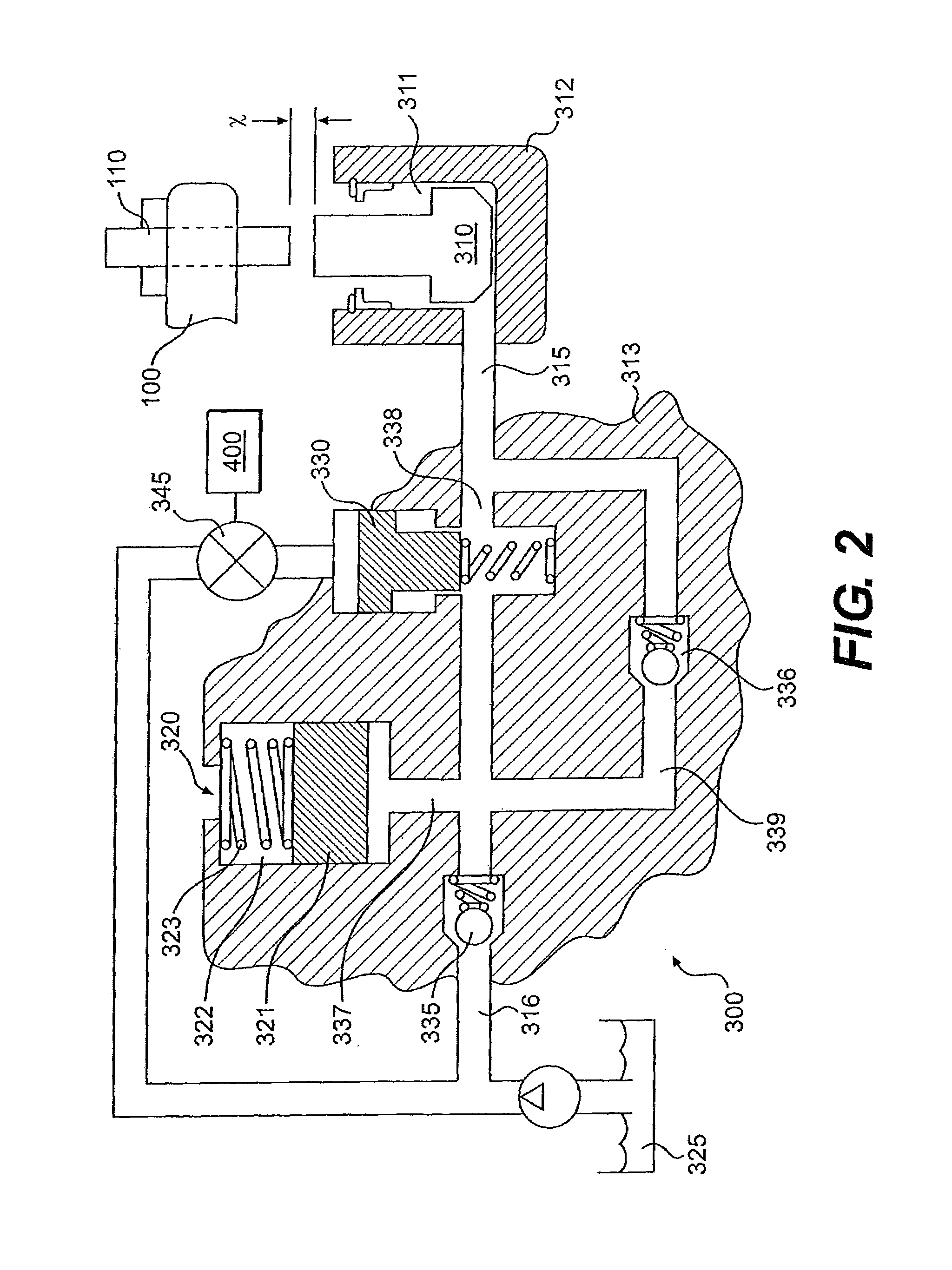
[0027]As embodied herein, the present invention includes both systems and methods of controlling the actuation of engine valves for auxiliary engine valve actuation events, such as, but not limited to, engine braking. Reference will now be made in detail to a first embodiment of the present invention, an example of which is illustrated in the accompanying drawings.

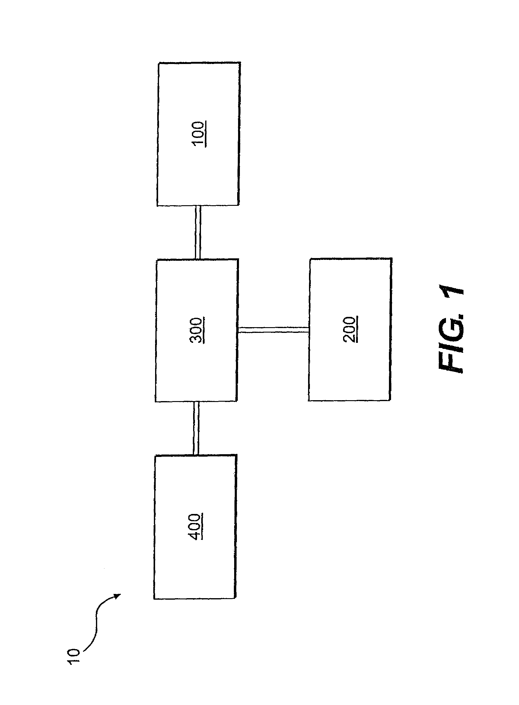
[0028]A first embodiment of the present invention is shown in FIG. 1 as valve actuation system 10. The valve actuation system 10 may include a means for imparting motion 100 operatively connected to a hydraulic valve actuation system 300, which in turn is operatively connected to one or more engine valves 200. The engine valves 200 may be exhaust valves, intake valves, or auxiliary valves. The motion imparting means 100 may include any combination of cam(s), push tube(s), rocker arm(s) or other valve train element(s) that provide an input motion to the hydraulic valve actuation system 300. For ease of discussion, the means...


PUM


Abstract

Apparatus and methods for hydraulic valve actuation of engine valves are disclosed. An exemplary embodiment of the present invention may include a lost motion piston assembly that transfers motion between first and second rocker arms to selectively provide auxiliary engine valve actuation motions to the engine valves for engine operations such as engine braking and exhaust gas recirculation. The lost motion piston assembly may reduce or eliminate transient loads that may otherwise be transmitted to engine valve train elements during the times that lost motions systems are turned on and off for auxiliary valve actuations.

Description

CROSS-REFERENCE TO RELATED APPLICATIONS[0001]The present application relates to, and claims the priority of, U.S. Provisional Patent Application Ser. No. 60 / 854,716, filed Oct. 27, 2006, which is entitled “Engine Brake Incorporating Transient Relief for Valvetrain and Method Thereof.”FIELD OF THE INVENTION[0002]The present invention relates to methods and apparatus for actuating engine valves in an internal combustion engine.BACKGROUND OF THE INVENTION[0003]Valve actuation in an internal combustion engine is required in order for the engine to produce positive power. During positive power operation, one or more intake valves may be opened to admit fuel and / or air into a cylinder for combustion. One or more exhaust valves may be opened to allow combustion gas to escape from the cylinder. Intake, exhaust, and / or auxiliary valves also may be opened during positive power at various times to recirculate gases for improved emissions.[0004]Valve actuation may also be required to produce au...

Claims


Application Information

Patent Timeline
Patent Type & Authority Patents(United States)
IPC IPC(8): F01L9/02
CPCF01L13/0036F01L13/065F02D9/06F02D13/04F01L2001/186F01L1/34F01L13/06F01M1/16
Inventor JANAK, ROBBRUGGIERO, BRIAN L.PRUSAK, JONATHAN W.
Owner JACOBS VEHICLE SYST
Learn More