Dual channel pulsed variable pressure hydraulic test apparatus

a hydraulic test and variable pressure technology, applied in the field of hydraulic testing apparatus, can solve the problems of inability to apply hydraulic fluid to the put at more than, the maximum rate at which hydraulic testing apparatus can apply pressure pulses is often too slow, and the pressure delay in the hydraulic line is minimized, the test is faster and flexible, and the effect of increasing the pressur

Inactive Publication Date: 2015-03-05
RABERT ARTHUR M
View PDF6 Cites 3 Cited by
  • Summary
  • Abstract
  • Description
  • Claims
  • Application Information

AI Technical Summary

Benefits of technology

[0010]The present invention is an enhanced pressure testing apparatus that is faster and more flexible than current designs. Pressure delays in the hydraulic lines are minimized by using hydraulic lines that are significantly larger in diameter than previous designs. For example, lines that are 1¼ inches in diameter are used in some embodiments for applications where ¼ inch diameter lines have typically been used in the past. A fluid accumulator is used to avoid pump output capacity delays by storing a volume of hydraulic fluid that is pre-pressurized while the control valve is closed, and then supplements the pump output when the control valve is open. Delays that might otherwise arise due to the enlarged volume of the hydraulic lines are thereby avoided.

Problems solved by technology

As testing requirements have become more demanding and sophisticated, for example requiring 360,000 pressure pulse cycles or more, the maximum rate at which hydraulic testing apparatus can apply pressure pulses has often proven to be too slow, due to pressure delays in the hydraulic lines and limitations in the operating speed of the solenoid valve.
In addition, systems such as the apparatus illustrated in FIG. 1 are limited to a single applied pressure, and are unable to apply hydraulic fluid to the PUT at more than one pressure during a test.

Method used


Image

  • Dual channel pulsed variable pressure hydraulic test apparatus
  • Dual channel pulsed variable pressure hydraulic test apparatus
  • Dual channel pulsed variable pressure hydraulic test apparatus

Examples


Embodiment Construction

[0036]The present invention is an enhanced pressure testing apparatus that is faster and more flexible than current designs. Pressure delays in the hydraulic lines are minimized by using hydraulic lines that are larger in diameter than previous designs. For example, lines that are 1¼ inches in diameter are used in some embodiments for applications where ¼ inch diameter lines have typically been used in the past.

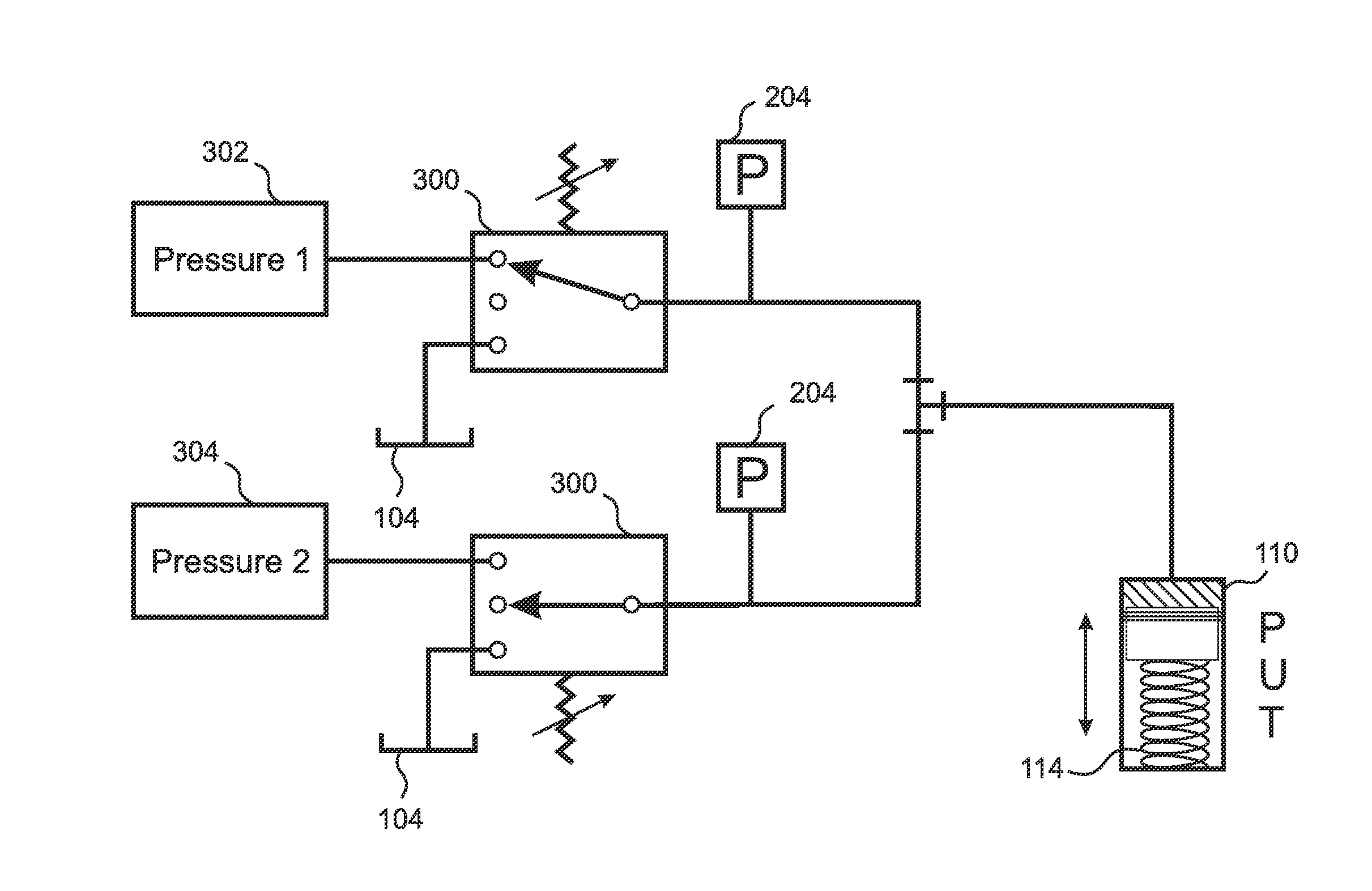
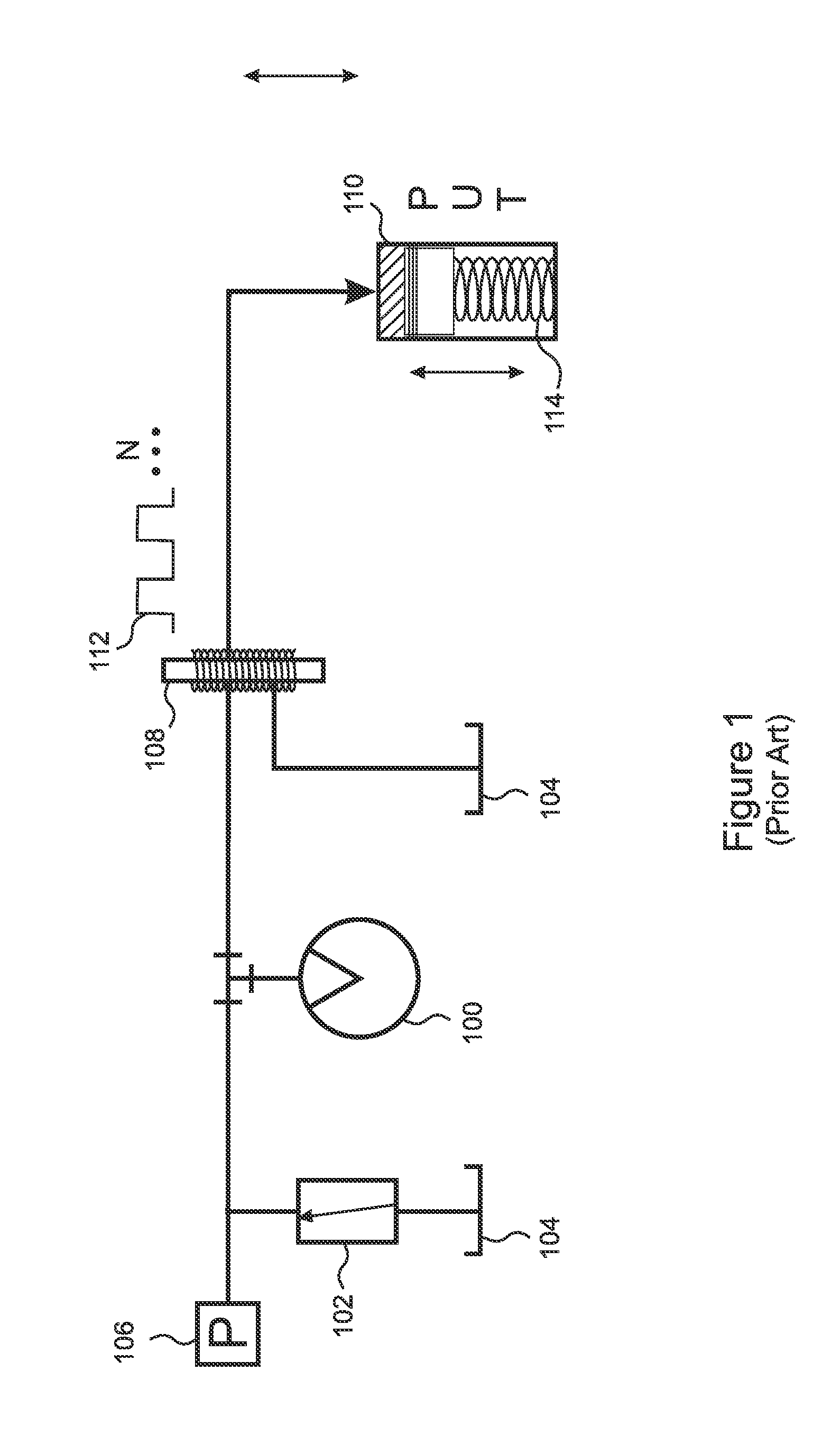
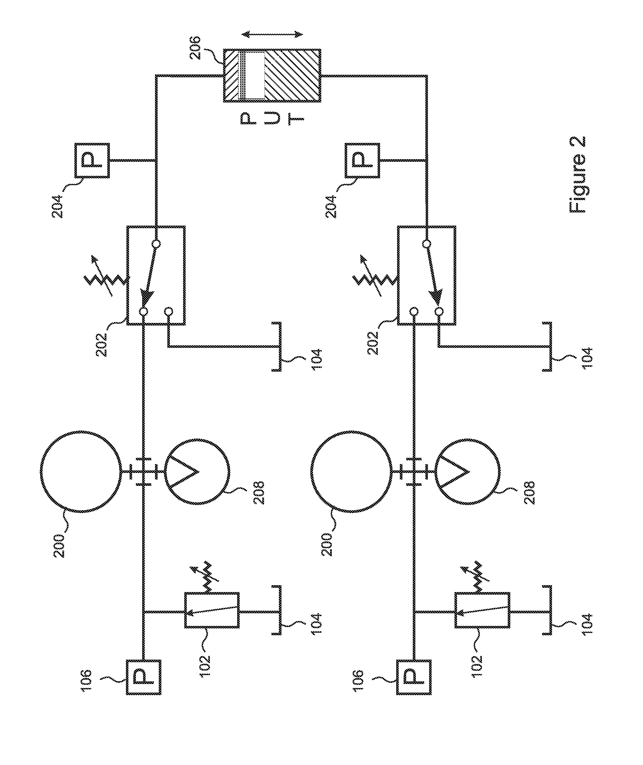
[0037]With reference to FIG. 2, rather than providing only a single pressure delivery channel, the present invention includes two pressure delivery channels, each of which includes its own pump, which can be a rotary pump 100 as shown in FIG. 1, or a variable-vane pump 208 as shown in FIG. 2. Each pressure delivery channels further includes a regulator 102 and control valve, which in some embodiments is a solenoid valve 108 and in other embodiments is a servo valve 202. As a result, a PUT 206 that requires separately applied pneumatic pressure to return to its initial configu...


PUM


Abstract

A fast and flexible pressure testing apparatus includes two parallel pressure channels having independent pumps and pressure regulators. Pressure pulse cycle times are minimized by using large diameter hydraulic lines. A fluid accumulator in each channel stores pre-pressurized fluid to avoid pressure delivery delays due to limited pump output. In embodiments, the outputs of the two delivery channels can be combined to deliver pressure pulses to the part under test (PUT) from either channel in any desired sequence, or one channel can be used to return the PUT to its initial status. Embodiments gate the pressure pulses using servo valves, which can have pressure outputs that are proportional to their control signals, thereby enabling shaped output pressure profiles according to shaping of the control signals. The pressure channels can be further split into first and second branches which set the ranges over which the channel output can be varied.

Description

RELATED APPLICATIONS[0001]This application claims the benefit of U.S. Provisional Application No. 61 / 812,798, filed Apr. 17, 2013, which is herein incorporated by reference in its entirety for all purposes.FIELD OF THE INVENTION[0002]The invention relates to hydraulic apparatus, and more particularly, to apparatus for pulsed pressure testing of hydraulic apparatus sealing components.BACKGROUND OF THE INVENTION[0003]Hydraulic systems are widely used in many industries. Examples include motor vehicle engines, braking systems, aeronautical control systems, industrial pumping systems, presses, rolling mills, earth-moving equipment, floor conveyors, agricultural machines, truck loading cranes, injection molding machines, marine hydraulics, and many others.[0004]So as to ensure reliability and longevity even under challenging conditions, it is often necessary to submit hydraulic designs to rigorous and prolonged pressure testing, so as to ensure that there is no excessive material fatigue...

Claims


Application Information

Patent Timeline
Patent Type & Authority Applications(United States)
IPC IPC(8): F15B1/033F15B21/08F15B21/12
CPCF15B1/033F15B21/12F15B2211/6309F15B2211/212F15B21/08G01N3/36G01N3/32G01N2203/0005G01N2203/0042G01N2203/0048G01N2203/0085
Inventor RABERT, ARTHUR M.
Owner RABERT ARTHUR M
Why Eureka
Try Eureka