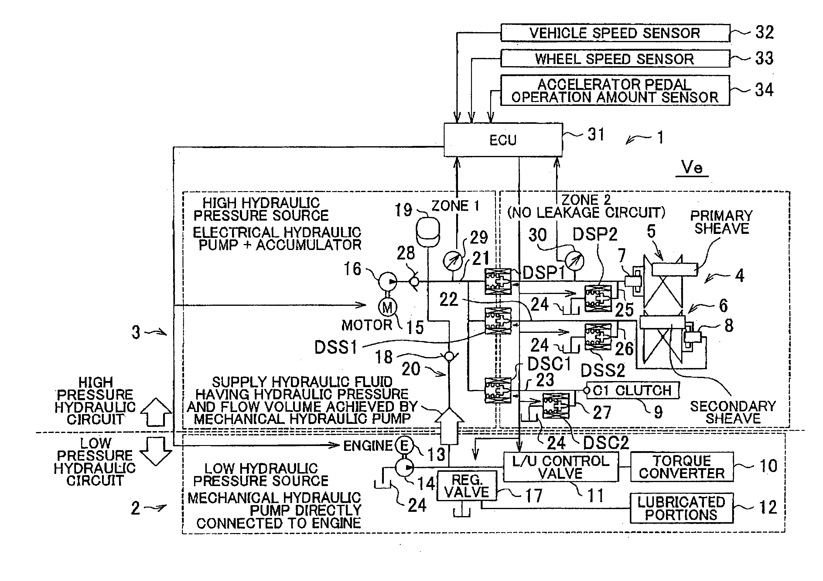
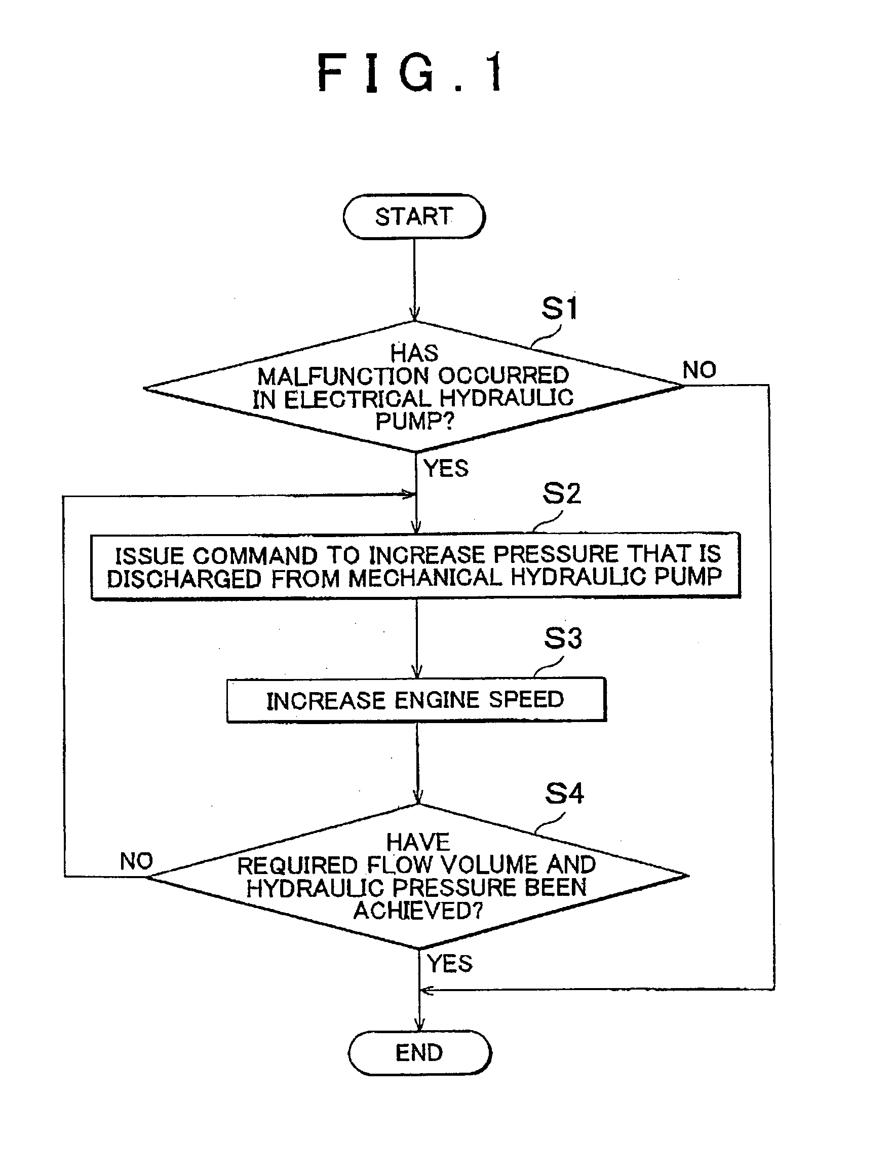
[0010]According to the first aspect of the invention described above, if the malfunction detection unit determines that the electrical hydraulic pump malfunctions, the
discharge pressure increasing unit increases the volume of hydraulic fluid that is discharged from the mechanical hydraulic pump and increases the hydraulic pressure that is generated by the mechanical hydraulic pump. Then, at least part of the hydraulic fluid of which the hydraulic pressure is increased to the relatively high hydraulic pressure is supplied to the high hydraulic pressure supplied portion through the
oil supply passage. As described above, if the electrical hydraulic pump malfunctions, it is possible to generate a relatively high hydraulic pressure with the use of the mechanical hydraulic pump, and to supply the hydraulic fluid having the relatively high hydraulic pressure to the high hydraulic pressure supplied portion. Also, the hydraulic fluid may be confined by the
oil supply passage. Therefore, it is possible to suppress or reduce a decrease in the hydraulic pressure in the high hydraulic pressure supplied portion. Also, it is possible to suppress or reduce shortage of the flow volume of the hydraulic fluid. As a result, it is possible to maintain the drive state as much as possible, and the vehicle is able to keep traveling.
[0012]According to the configuration described above, the
discharge pressure increasing unit increases the rotational speed of the engine in response to a command to increase the hydraulic pressure that is supplied from the mechanical hydraulic pump. Because the mechanical hydraulic pump is driven by the engine, if the rotational speed of the engine is increased, the rotational speed of the mechanical hydraulic pump is increased and the hydraulic pressure that is generated by the mechanical hydraulic pump is increased.
[0014]According to the configuration described above, the input torque limiting unit calculates the upper limit input torque which is the upper limit of torque that is allowed to be input in the high hydraulic pressure supplied portion based on the volume or the hydraulic pressure of the hydraulic fluid that is allowed to be supplied to the high hydraulic pressure supplied portion, and limits the torque that is input from the engine to the high hydraulic pressure supplied portion to the upper limit input torque. Therefore, it is possible to transmit torque and change the speed ratio within the torque range and speed ratio range that correspond to the range of hydraulic pressure that may be actually supplied to the high hydraulic pressure supplied portion or the range of volume of hydraulic fluid that may be actually supplied to the high hydraulic pressure supplied portion. In other words, it is possible to avoid the situation where a torque that falls outside the range of torque that may be transmitted at the hydraulic pressure that is actually supplied to the high hydraulic pressure supplied portion or at the volume of hydraulic fluid that is actually supplied to the high hydraulic pressure supplied portion. Therefore, it is possible to maintain the drive state as much as possible, and the vehicle is able to keep traveling.
[0016]According to the configuration described above, the
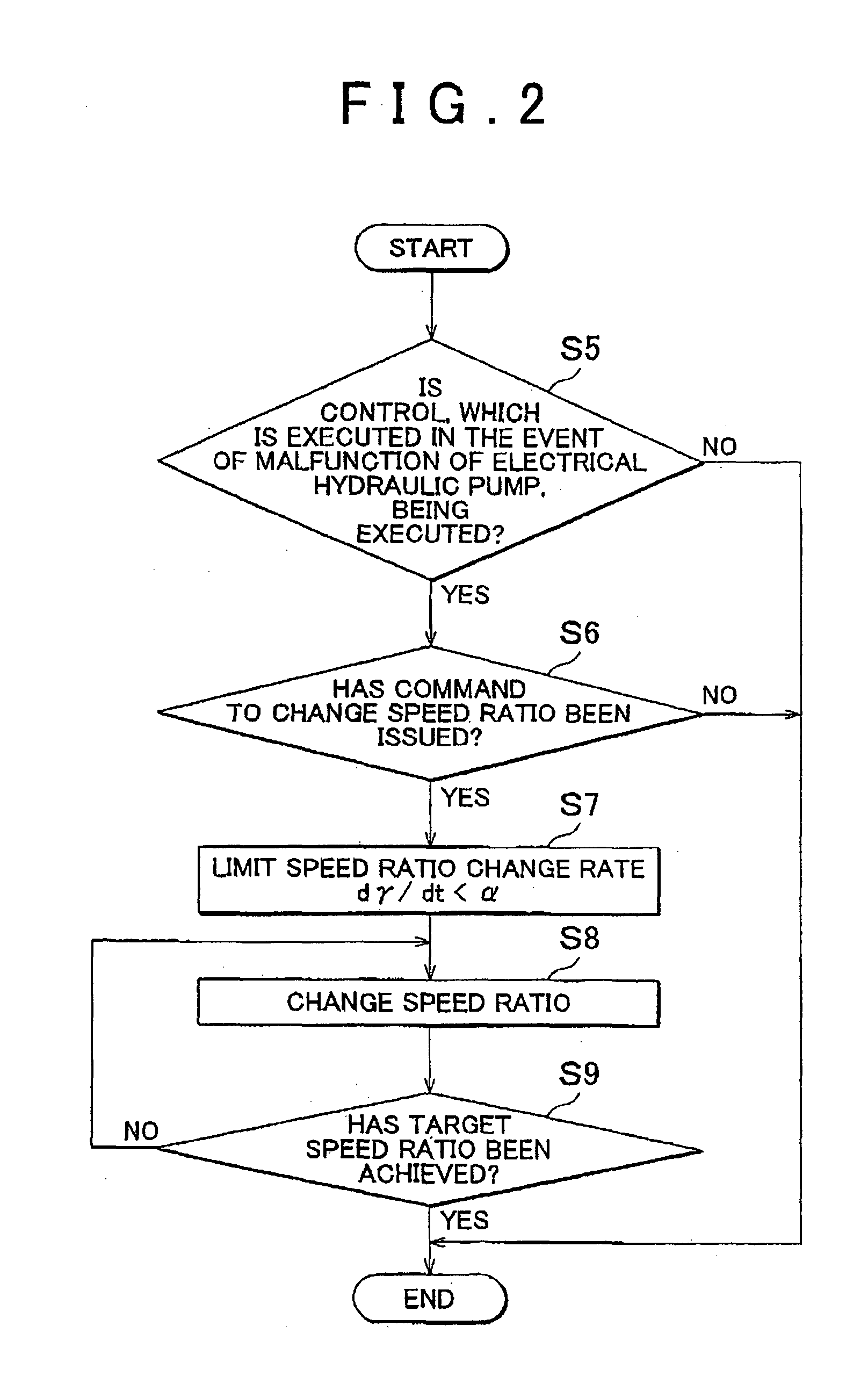
continuously variable transmission is supplied with a relatively high hydraulic pressure that is generated by the mechanical hydraulic pump instead of the electrical hydraulic pump in which a malfunction has occurred. When the speed ratio change command is provided to the
continuously variable transmission, the rate of change in the speed ratio is limited to a value equal to or lower than the value that is determined based on the parameter that indicates the operating state of the mechanical hydraulic pump. Therefore, it is possible to change the speed ratio at the speed ratio change rate that corresponds to the operating state of the mechanical hydraulic pump. Also, it is possible to achieve the hydraulic pressure at which the speed ratio can be changed. As a result, it is possible to maintain the drive state as much as possible, and the vehicle is able to keep traveling.
[0018]According to the configuration described above, the continuously variable transmission is a belt continuously variable transmission, and the belt continuously variable transmission is supplied with a relatively high hydraulic pressure that is generated by the mechanical hydraulic pump instead of the electrical hydraulic pump in which a malfunction has occurred. If a speed ratio change command is provided to the belt continuously variable transmission, the range of speed ratio change is limited by the speed ratio range limiting unit. Therefore, it is possible to change the speed ratio to a speed ratio that corresponds to the operating state of the mechanical hydraulic pump. Also, it is possible to achieve the hydraulic pressure at which the speed ratio can be changed. As a result, it is possible to maintain the drive state as much as possible, and the vehicle is able to keep traveling.
[0022]According to the configuration described above, the malfunction detection unit determines that the electrical hydraulic pump malfunctions if the difference between the hydraulic pressure that is actually supplied to the high hydraulic pressure supplied portion and the command hydraulic pressure for the electrical hydraulic pump is equal to or larger than a predetermined value. Therefore, it becomes easier to determine whether the electrical hydraulic pump malfunctions.

