Ignition apparatus for an internal combustion engine

a technology for internal combustion engines and ignition apparatuses, which is applied in mechanical apparatus, machines/engines, spark plugs, etc., can solve the problems of difficult to install a plurality of such magnetrons on the internal combustion engine main body, and difficult for magnetrons of large weights to withstand or endure vibrations applied thereto

Inactive Publication Date: 2010-09-14
MITSUBISHI ELECTRIC CORP
View PDF11 Cites 32 Cited by
  • Summary
  • Abstract
  • Description
  • Claims
  • Application Information

AI Technical Summary

Benefits of technology

[0014]According to the ignition apparatus for an internal combustion engine of the present invention, the microwave oscillation device is made into a solid state or is formed of solid state components, so there is obtained an advantageous effect that the microwave oscillation device is able to withstand or endure a vibration environment of a vehicle.

Problems solved by technology

Accordingly, in an internal combustion engine main body composed of a plurality of cylinders, it is necessary to provide a magnetron for each cylinder that requires a large space for installation thereof, and hence there has been a problem that in actuality, it is difficult to install a plurality of such magnetrons on the internal combustion engine main body.
In addition, in case where such an ignition apparatus is installed on a vehicle, there has been another problem that it is difficult for the magnetrons of large weights to withstand or endure vibrations applied thereto.

Method used


Image

  • Ignition apparatus for an internal combustion engine
  • Ignition apparatus for an internal combustion engine
  • Ignition apparatus for an internal combustion engine

Examples


embodiment 1

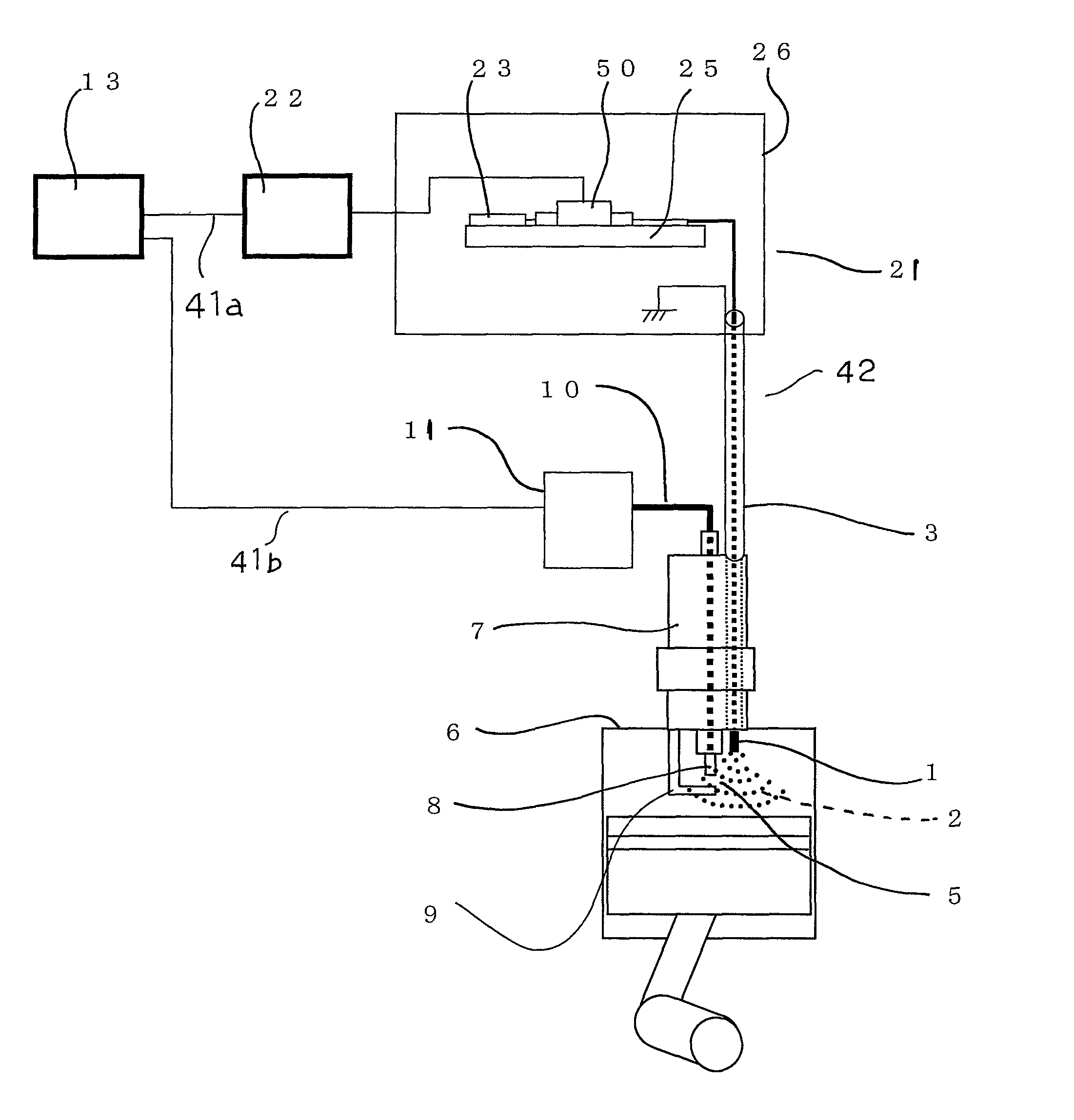
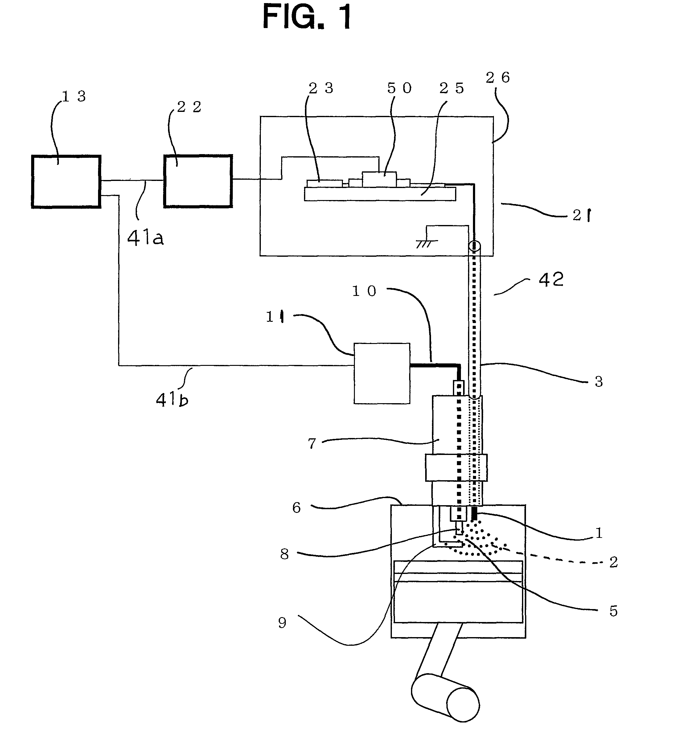
[0021]Referring to the drawings and first to FIG. 1, there is shown a block diagram of an ignition apparatus 42 for an internal combustion engine (hereinafter abbreviated as an ignition apparatus) according to a first embodiment of the present invention. FIG. 2 is an electric circuit diagram of a microwave oscillation device 21 shown in FIG. 1.

[0022]This ignition apparatus 42 is provided for each of cylinders 6, and includes a spark plug 7 having an ignition and discharge part 5, a high voltage generation power supply 11 that is connected to the ignition and discharge part 5 through a connection cable 10, a control unit 13 that is electrically connected the high voltage generation power supply 11 through a control unit line 41b, a microwave antenna 1 that is arranged in the vicinity of the ignition and discharge part 5 and irradiates a microwave thereby to form a plasma generation region 2, a microwave oscillation device 21 that is electrically connected to the microwave antenna 1 t...

embodiment 2

[0034]FIG. 3 is a block diagram of an ignition apparatus for an internal combustion engine according to a second embodiment of the present invention.

[0035]In this second embodiment, a high voltage generation power supply 11 has a control circuit part 52, a primary coil 53, a iron core 54, and a secondary coil 55 received in a container 51. By the use of a coupling member 56, this high voltage generation power supply 11 is integrally coupled with a microwave oscillation device 21 in which a substrate 25, a resonator 23, and an amplifier circuit 50 are received in a casing 26. The high voltage generation power supply 11 and the microwave oscillation device 21 thus integrally coupled with each other cooperate to constitute a power supply and oscillation main body 60. This power supply and oscillation main body 60 with a portion of a spark plug 7 exposed from a cylinder 6 is covered with a microwave shield member 46 through an outer frame casing 61.

[0036]The high voltage generation powe...


PUM


Abstract

An ignition apparatus for an internal combustion engine is small in size and has high reliability capable of withstanding or enduring a vibration environment of a vehicle to which the ignition apparatus is installed. The ignition apparatus includes a spark plug that has its tip end portion presented in the interior of a cylinder of an internal combustion engine main body, a high voltage generation power supply that serves to apply a high voltage to the spark plug, a microwave oscillation device that has an amplifying element for generating a microwave, and a microwave antenna that is mounted on the spark plug, irradiates the micro wave generated from the microwave oscillation device to the interior of the cylinder, thereby forming a plasma generation region around discharge electrodes of the spark plug. The microwave oscillation device is made into a solid state.

Description

BACKGROUND OF THE INVENTION[0001]1. Field of the Invention[0002]The present invention relates to an ignition apparatus for an internal combustion engine in which a plasma generation region is formed around discharge electrodes of a spark plug.[0003]2. Description of the Related Art[0004]In the past, there has been known an ignition apparatus for an internal combustion engine which includes spark plugs each of which has its tip end portion presented in the interior of a corresponding cylinder of an internal combustion engine main body, a high voltage generation power supply that serves to apply a high voltage to the spark plugs, a magnetron that generates a microwave, and a microwave antenna that is mounted on each of the spark plugs, irradiates the microwave generated from the magnetron to the interior of a corresponding cylinder, thereby forming a plasma generation region around discharge electrodes of the spark plug (see, for example, a first patent document: Japanese patent appli...

Claims


Application Information

Patent Timeline
Patent Type & Authority Patents(United States)
IPC IPC(8): H01T13/08
CPCF02P23/045F02P15/08
Inventor IDOGAWA, TAKASHIMURATA, SHIGEMISHIMIZU, TAKESHI
Owner MITSUBISHI ELECTRIC CORP
Why Eureka
Try Eureka