Joining device for joining two assemblies, for example for a stator of a turbomachine

a technology of joining device and assembly, which is applied in the direction of machines/engines, couplings, liquid fuel engines, etc., can solve the problems of difficult, if not impossible, assembly by operators, and the possibility of bringing the connecting member, so as to avoid the detrimental bending effect, precise relative positioning, and accurate final positioning of the connecting member

Active Publication Date: 2010-09-14
SN DETUDE & DE CONSTR DE MOTEURS DAVIATION S N E C M A
View PDF8 Cites 7 Cited by
  • Summary
  • Abstract
  • Description
  • Claims
  • Application Information

AI Technical Summary

Benefits of technology

[0015]The joining device according to the invention has the particular feature of enjoying all of the advantages relating to the embodiments of the prior art, without suffering from their disadvantages.
[0016]Specifically, it should first of all be emphasized that the joining device is of a design which allows it to be made of small-sized elements, in that the presence of a two-lug clevis avoids the detrimental bending effects encountered in the single-lug solutions of the prior art.
[0017]In addition, it is advantageously possible to achieve accurate final positioning of the connecting member with respect to the clevis given that this member is kept fixedly in contact with one of the two lugs of this clevis. As a result, this makes it possible to obtain very precise relative positioning between the first and second assemblies bearing this joining device according to the invention.
[0019]Finally, it must therefore be understood that the separation between the two lugs is far greater than the thickness of the connecting member because this connecting member is situated some distance from the first clevis lug in the assembled position. Thus, this particular feature offers the advantage of giving the operator a great deal of scope as to how he introduces the member into the clevis, this insertion of course now no longer being restricted to the application of a translational movement parallel to the orientation of the clevis as it was before.

Problems solved by technology

The disadvantage of this kind of set up lies in the fact that it is conceivable only with a very small amount of clearance between the various components before the screw / nut assembly is tightened.
This is because an excessive initial separation between the lugs of the clevis would, upon tightening, squeeze these lugs together and stress them, thereby weakening them.
Furthermore, with this combination, it is only possible to bring the connecting member parallel to the lugs of the clevis as it is being introduced between these lugs, namely at right angles to the axes of the clevis holes, by applying a translational movement parallel to a direction known as the clevis orientation direction.
This inevitably makes it difficult, if not impossible, under certain circumstances as described in the example below, for an operator to assemble and of necessity entails that the components be positioned very accurately relative to one another in order to be able to achieve the aforementioned introduction.
Nonetheless, the major disadvantage with this type of setup stems from there being a degree of freedom associated with the connecting member situated some distance from the two clevis lugs, giving this same member the ability to move along the pin system.
As a result, because this connecting member is not pressed against the clevis lugs, it is therefore impossible to guarantee accurate positioning of the second assembly with respect to the first assembly.
In addition, if a clearance is left between the pin system and the through hole made in the connecting member, particularly with a view to accommodating some degree of uncertainty over the positioning prior to the introduction of the pin system through this hole, the mechanical joint obtained then becomes extremely sensitive to vibrations.
However, the lug and the member experience a significant amount of bending as a result of the asymmetry of the fastening, thus creating a high bending moment.
In addition, in order to transmit loads of the same order of magnitude, this type of fastening requires components which are overengineered by comparison with those of which the abovementioned two-lug clevis devices are made, and as a result causes problems of space.

Method used


Image

  • Joining device for joining two assemblies, for example for a stator of a turbomachine
  • Joining device for joining two assemblies, for example for a stator of a turbomachine
  • Joining device for joining two assemblies, for example for a stator of a turbomachine

Examples


Embodiment Construction

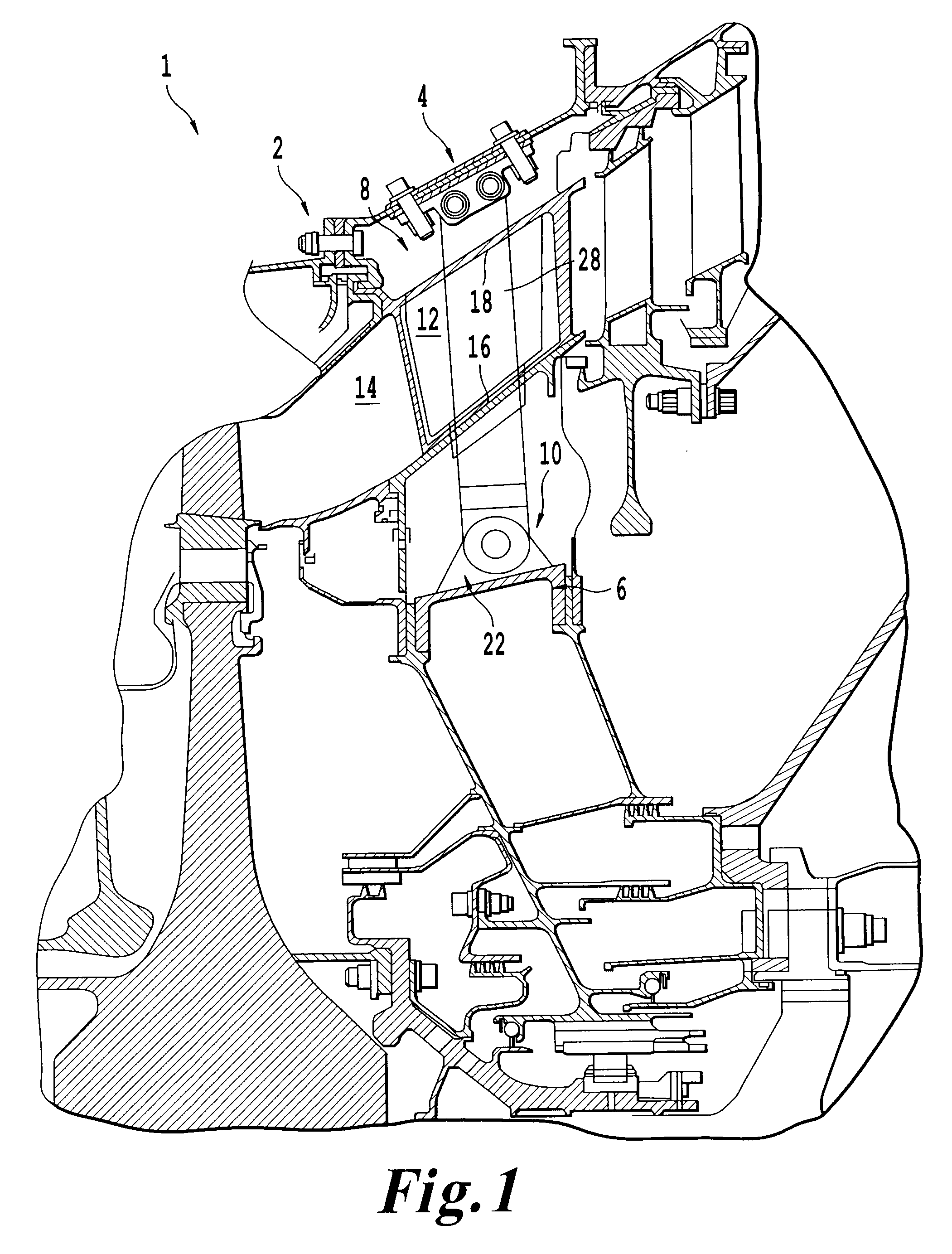
[0042]FIG. 1 shows part of a turbomachine 1 according to one preferred embodiment of the present invention and, more particularly, a turbomachine module 2 which in this instance is a high-pressure or HP turbine of the turbomachine, which for its part is in the form of an aircraft turbojet engine.

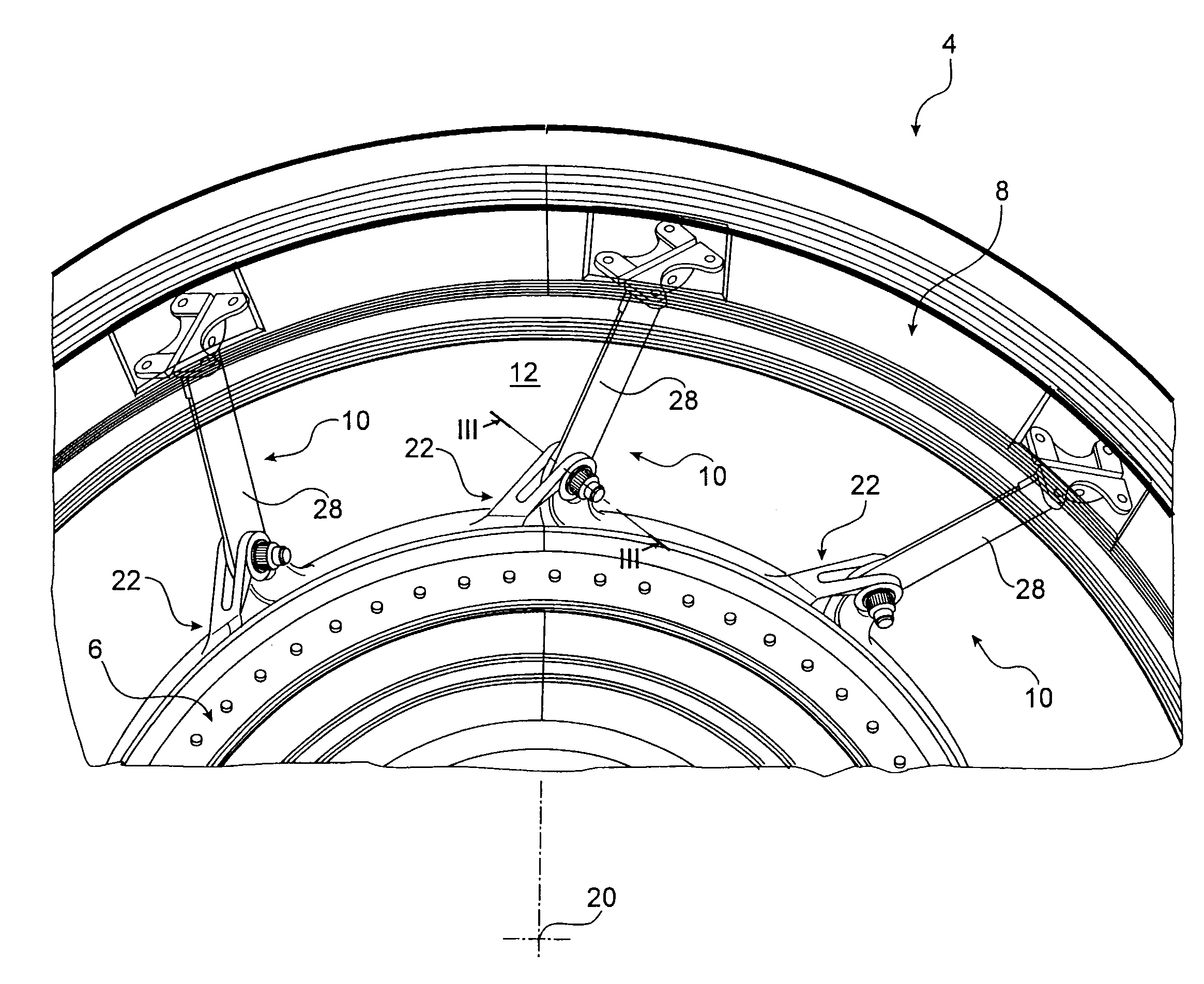
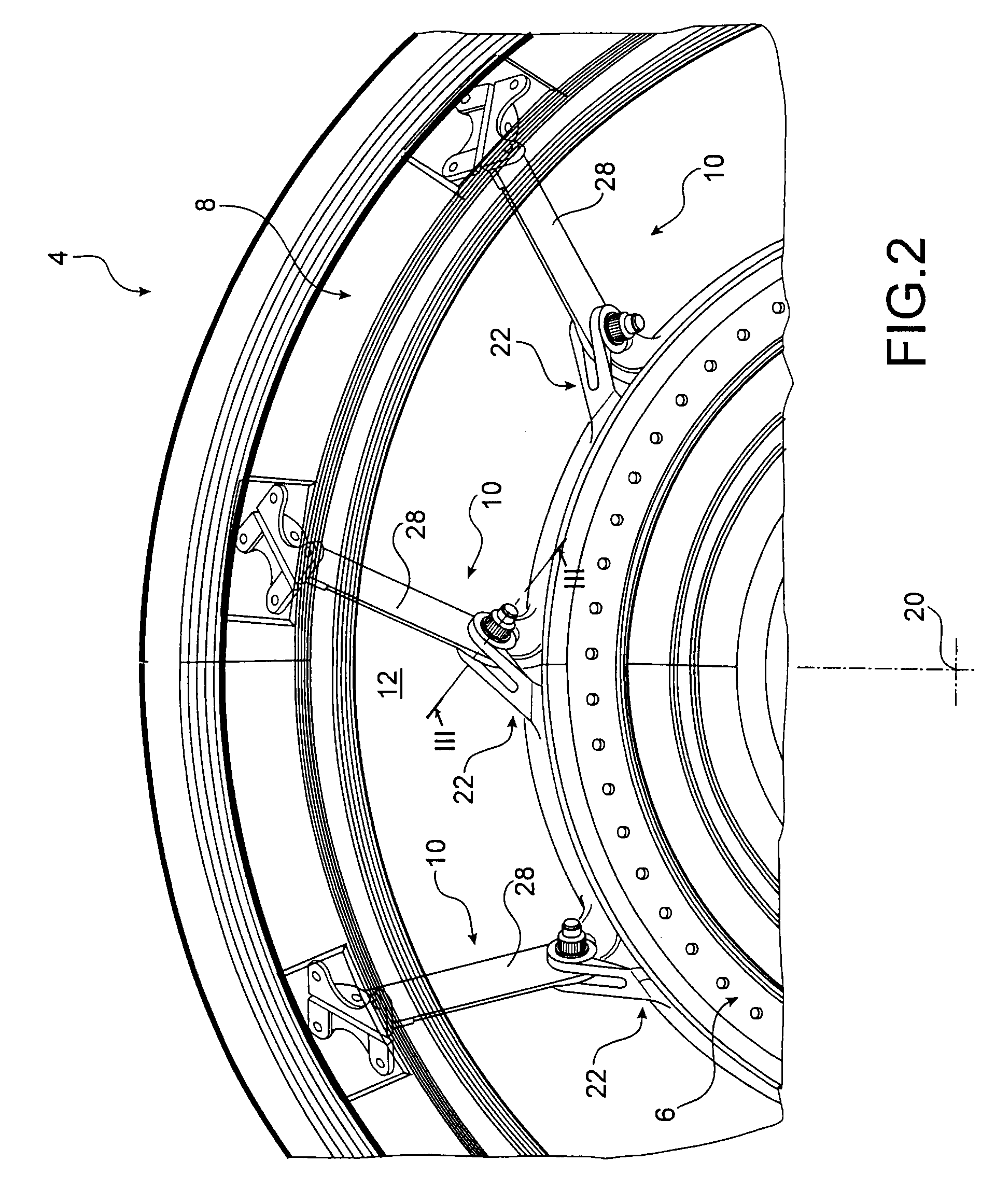
[0043]The module 2 comprises a stator partially composed of a joint 4 which also forms part of the subject of the present invention, this joint 4 in general comprising a first assembly 6 and a second assembly 8 which are annular and concentric about an axis of the turbomachine (not depicted) which also corresponds to the axis of these assemblies 6, 8. As will be detailed hereinbelow, the assemblies 6, 8 are fixedly attached to one another by a number of joining devices 10 spaced circumferentially apart, uniformly, also termed as “cyclically”.

[0044]As is visible in FIG. 1, the first and second assemblies 6, 8 between them define an annular space 12 forming a transverse portion of the primary ...


PUM


Abstract

A joining device including a clevis and a connecting member is disclosed. The connecting member includes a through hole which is housed between a first and a second lug of the clevis. These lugs respectively have a first clevis hole and a second clevis hole. The device further includes a shear pin system passing through each of the holes and includes a threaded end collaborating with a nut system which abuts against the second lug. The shear pin system includes a widened portion passing through the first hole and forming a shoulder situated between the two lugs. The member is situated away from the first lug. A first side of the member is pressed against the shoulder and a second side of the member is pressed against the second lug.

Description

TECHNICAL FIELD[0001]The present invention relates in general to a joining device for joining two assemblies of the type comprising a clevis intended to be attached to a first assembly and a connecting member intended to be attached to a second assembly.[0002]The invention applies particularly although not exclusively to the field of turbomachines, preferably taking the form of a turbojet engine for an aircraft, for example for connecting together two annular and concentric assemblies of a turbine or compressor stator.PRIOR ART[0003]Various joining devices of the type mentioned hereinabove are known from the prior art.[0004]First, a conventional device known as a two-lug clevis is known. This is used to clamp the connecting member between the two lugs using a screw / nut combination passing through the device. In this case, loads are transferred essentially by the rubbing of the two opposing faces of the connecting member against the respective internal faces of the two lugs between w...

Claims


Application Information

Patent Timeline
Patent Type & Authority Patents(United States)
IPC IPC(8): F04D29/44
CPCF01D25/162F05B2260/301Y10T403/32918Y10T403/32893Y10T403/32221
Inventor DRELON, GODEFROY FRANCIS FREDERICPABION, PHILIPPE JEAN-PIERREPRESTEL, SEBASTIEN JEAN LAURENTSOUPIZON, JEAN-LUC
Owner SN DETUDE & DE CONSTR DE MOTEURS DAVIATION S N E C M A
Why Eureka
Try Eureka