
Rechargeable battery module having a cooling mechanism

a technology of rechargeable batteries and cooling mechanisms, which is applied in the direction of cell components, electrochemical generators, flat cell groups, etc., can solve the problems of deteriorating performance and increasing temperature inside the unit cell, and achieve the effect of maximizing cooling efficiency

Inactive Publication Date: 2010-09-14
SAMSUNG SDI CO LTD
View PDF42 Cites 41 Cited by
  • Summary
  • Abstract
  • Description
  • Claims
  • Application Information

AI Technical Summary

Benefits of technology

The present invention provides a rechargeable battery module with maximized cooling efficiency. The module includes multiple unit cells that are mounted in a housing and cooled by a coolant circulating inside the housing. The unit cells are arranged at a slant angle with respect to the coolant flow, and can be positioned along a line or in a cell series. The housing has protrusions on its internal surface, which can be regularly or irregularly formed at predetermined intervals. The supportive plate inside the housing has protrusions or corrugated portions. The battery module can be used to drive a motor.

Problems solved by technology

The heat generated at the unit cells may also cause the temperature inside the unit cells to increase, resulting in explosion thereof.
Particularly, since a battery module for an HEV is charged and discharged by a high current, it may have deteriorated performance due to the heat generated by the internal reaction of a rechargeable battery.

Method used


Image

  • Rechargeable battery module having a cooling mechanism
  • Rechargeable battery module having a cooling mechanism
  • Rechargeable battery module having a cooling mechanism

Examples


first embodiment

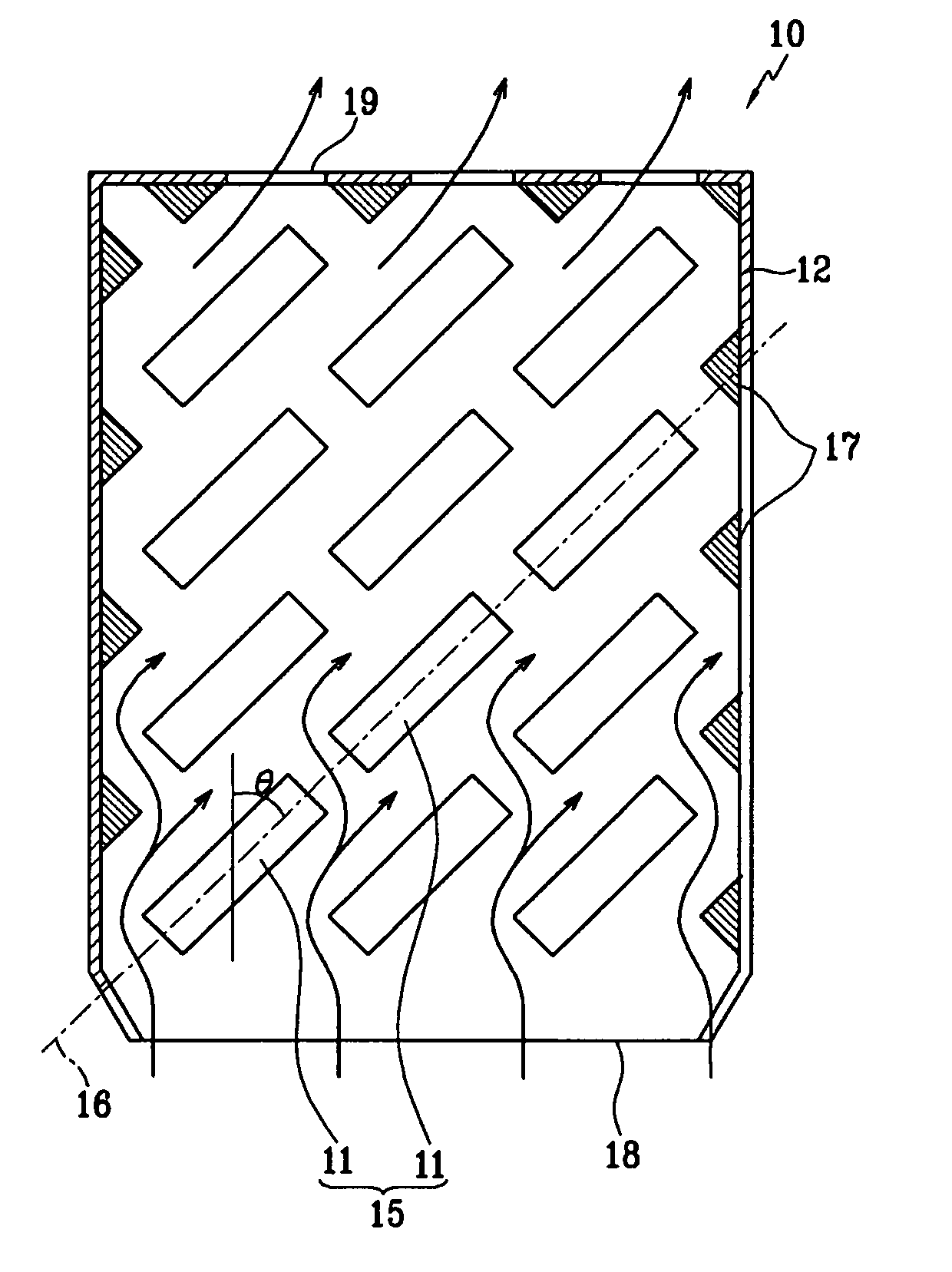
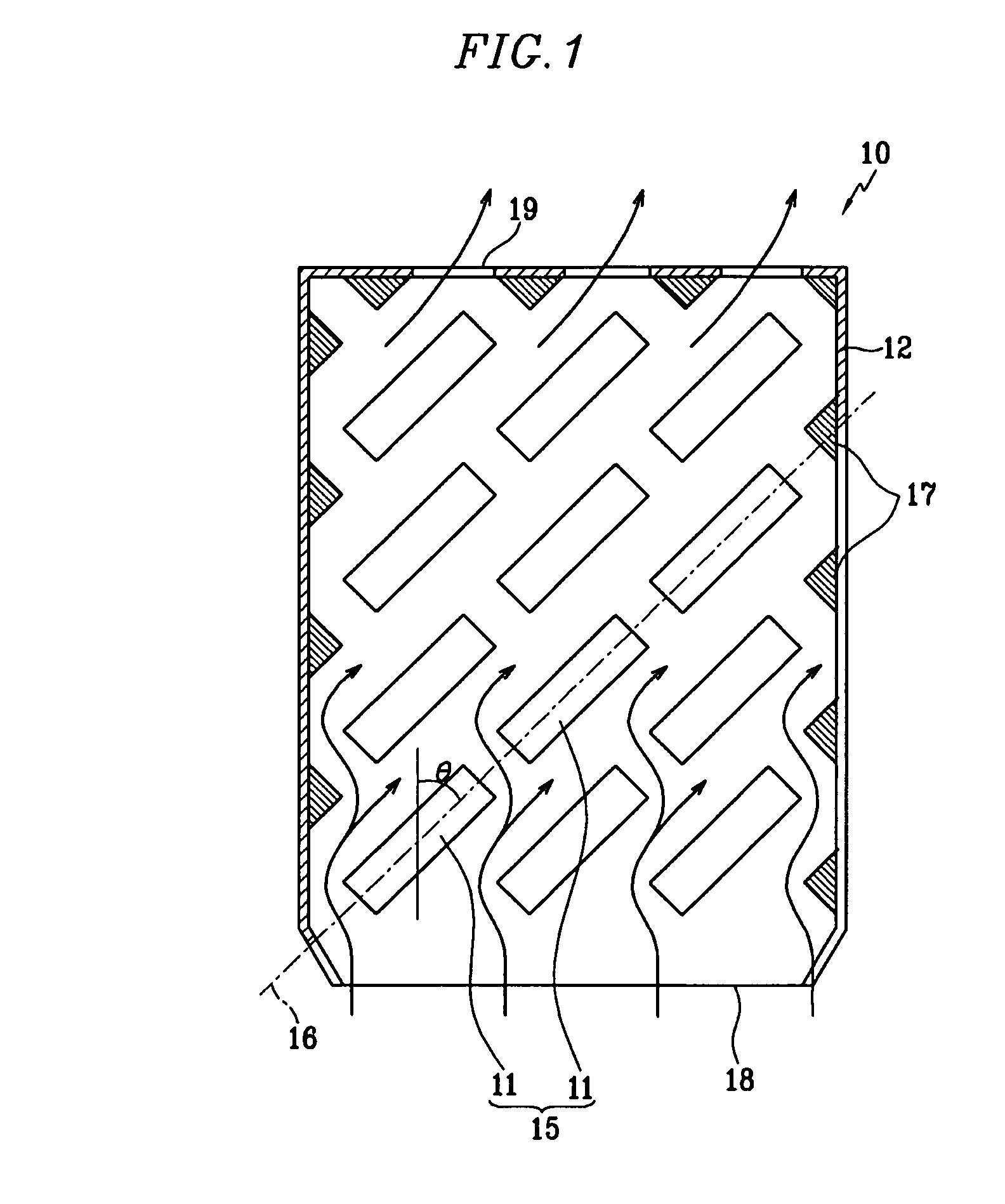
[0030]FIG. 1 is a schematic planar cross-sectional view illustrating the structure of a rechargeable battery module according to the present invention.

[0031]Referring to the drawing, a rechargeable battery module 10 includes a plurality of unit cells 11, which include an electrode assembly including positive and negative electrodes and a separator interposed therebetween and that generates electricity, and a housing 12, in which the unit cells 11 are mounted and air as a coolant (indicated by the arrows) is circulated.

[0032]According to this embodiment of the present invention, a prismatic rechargeable battery is used for each unit cell 11. The prismatic unit cells 11 are arranged at predetermined intervals inside the housing 12 to form a cell series 15. A plurality of the cell series 15 are disposed inside the housing 12, and the unit cells 11 in each cell series 15 are arranged at a predetermined angle (θ) with respect to the cooling airflow entering the housing 12.

[0033]In additi...

second embodiment

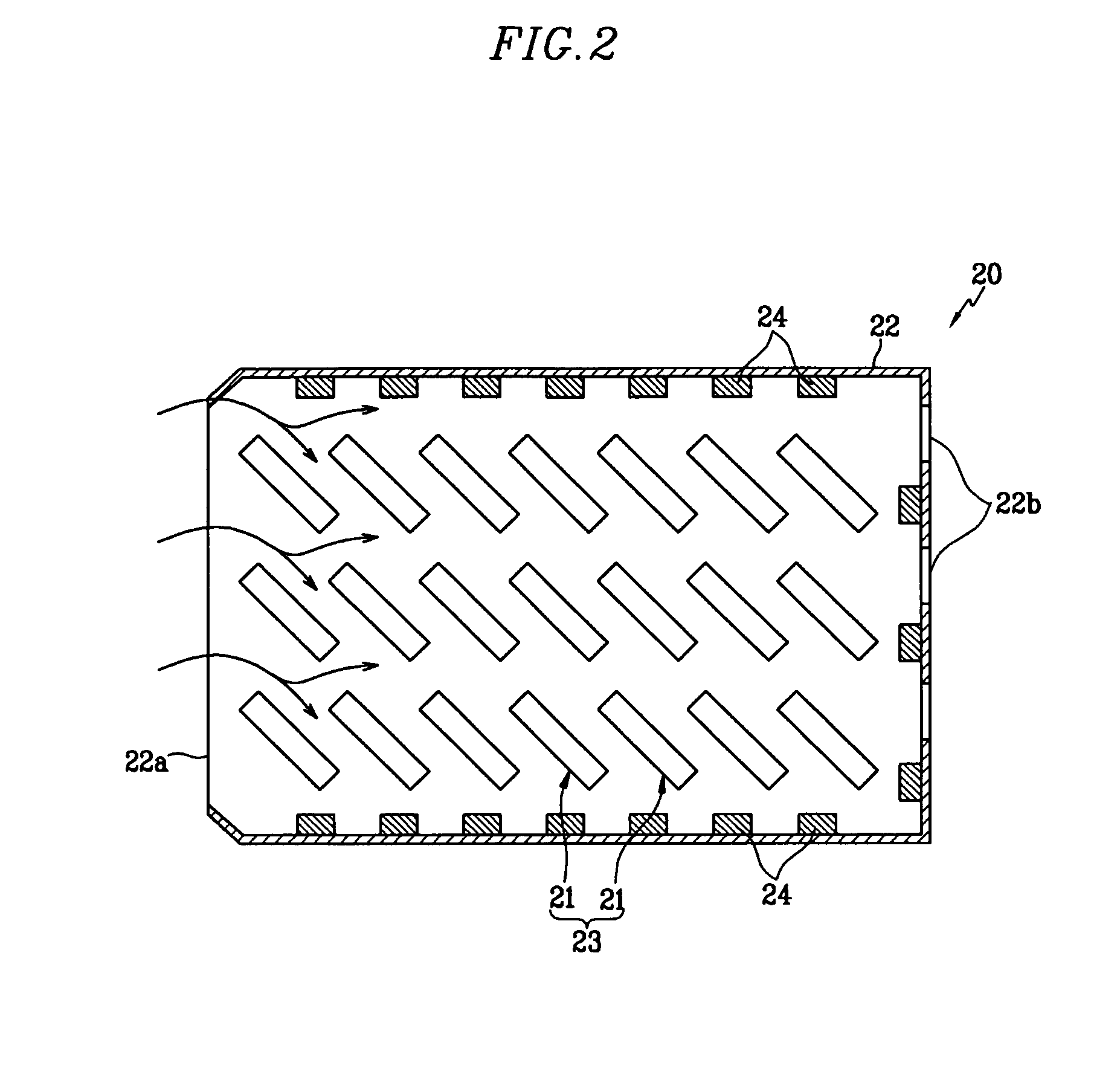
[0039]FIG. 2 is a planar cross-sectional view illustrating a rechargeable battery module according to the present invention.

[0040]Referring to the drawing, the rechargeable battery module 20 has a plurality of cell series 23 in which a plurality of unit cells 21 are disposed in parallel inside a housing 22. The housing 22 has an inlet 22a through which the cooling air enters and an outlet 22b through which the cooling air exits, on two opposing sides thereof. The housing 22 also has protrusions 24 at particular intervals on the internal wall thereof that are not related to the disposition structure of the unit cells 21.

[0041]Referring to FIG. 3, the protrusions 24 according to this embodiment of the present invention have a cylindrical shape, but their height from bottom to top can vary, depending on the interval between the housing 22 and the unit cells 21. Therefore, the protrusions 24 are formed to have an appropriate height according to the design of the rechargeable battery mod...


PUM

PropertyMeasurementUnit
angleaaaaaaaaaa
temperatureaaaaaaaaaa
angleaaaaaaaaaa

Abstract

A rechargeable battery module includes a plurality of unit cells; and a housing in which the unit cells are mounted and in which a coolant for controlling the temperature in the housing circulates. The unit cells are disposed in the housing on a slant at a predetermined angle with respect to an inflow of the coolant.

Description

CROSS-REFERENCE TO RELATED APPLICATION[0001]This application claims priority to and the benefit of Korean Patent Application No. 10-2005-0024867 filed in the Korean Intellectual Property Office on Mar. 25, 2005, the entire content of which is incorporated herein by reference.BACKGROUND OF THE INVENTION[0002]Unlike non-rechargeable batteries, rechargeable batteries can be repeatedly charged and discharged. Lower power batteries in which battery cells are made into a battery pack are used as the power source for various portable electronic devices such as cellular phones, laptop computers, and camcorders. Larger battery packs which are formed by connecting several to tens of the rechargeable battery cells may be suitable for motor driven devices such as hybrid electric vehicles.[0003]Rechargeable batteries may be classified into different categories based on external shape, for example, cylindrical and prismatic shapes.[0004]Such a rechargeable battery is assembled in series by connec...

Claims


Application Information

Patent Timeline
Patent Type & Authority Patents(United States)
IPC IPC(8): H02J7/04H02J7/16H01M10/60H01M10/613H01M10/617H01M10/625H01M10/647H01M10/651H01M10/6557H01M10/6562H01M10/6566H01M10/6568H01M50/204
CPCH01M2/1072H01M10/4207H01M10/5073H01M10/5032H01M10/5067H01M10/5004H01M10/6563H01M10/647H01M10/6566H01M10/613Y02E60/10H01M50/204H01M50/20
Inventor CHO, KYU-WOONG
Owner SAMSUNG SDI CO LTD
Learn More