Optical detection system using electromagnetic radiation to detect presence or quantity of analyte

an optical detection system and electromagnetic radiation technology, applied in the field of optical detection systems using electromagnetic radiation to detect the presence or quantity of analytes, can solve the problems of reduced cost and complexity of ordinary consumers, affecting the use affecting the sensitiveness and accuracy of optical detection systems,

Active Publication Date: 2010-09-14
KIMBERLY-CLARK WORLDWIDE INC
View PDF227 Cites 50 Cited by
  • Summary
  • Abstract
  • Description
  • Claims
  • Application Information

AI Technical Summary

Problems solved by technology

Unfortunately, conventional optical detection systems generally suffer from at least one of two major problems.
One problem is that the optical detection system, although sensitive and accurate, is too expensive and complex for use by ordinary consumers, such as non-technical personnel at doctor's offices, clinics, home, rest homes, etc.
However, such systems typically achieve a reduction in cost and complexity through a concurrent loss in sensitivity.
Although such a loss in sensitivity is not necessarily critical in all applications, it becomes increasingly problematic when the system is used in conjunction with membrane-based assay devices.
Due to such a low analyte concentration, the level of background interference (i.e., “noise”) may simply be too great relative to the detection signal to achieve an accurate result.

Method used


Image

  • Optical detection system using electromagnetic radiation to detect presence or quantity of analyte
  • Optical detection system using electromagnetic radiation to detect presence or quantity of analyte
  • Optical detection system using electromagnetic radiation to detect presence or quantity of analyte

Examples


example 1

[0086]The ability to form an optical detection system in accordance with the present invention was demonstrated. Initially, a nitrocellulose membrane (SHF-120, Millipore Corp. of Bedford, Mass.) was provided that was laminated to a Mylar® film support. The Mylar® film was attached directly to an electroluminescent (EL) device using a transparent adhesive obtained from Adhesives Research of Glen Rock, Pa. under the name “ARclear 8154.” Care was taken to ensure the absence of bubbles, dust, and contaminants. The EL device was made by BKL, Inc. of Burr Ridge, Ill., and had a size of 60 millimeters×300 millimeters. In addition, the EL device also had a dual, broad emission maxima of 482 and 580 nanometers to give “white” light emission.

[0087]Goldline™ (a polylysine solution obtained from British Biocell International) was striped onto the membrane to form a calibration zone. Monoclonal antibody reactive toward C-reactive protein (BiosPacific, Inc., concentration of 1 milligram per milli...

example 2

[0090]The ability to form an optical detection system in accordance with the present invention was demonstrated. Initially, a nitrocellulose membrane (SHF-120, Millipore Corp. of Bedford, Mass.) was provided that was laminated to a Mylar®) film support. The Mylar® film was attached directly to an electroluminescent (EL) device using a transparent adhesive obtained from Adhesives Research of Glen Rock, Pa. under the name “ARclear 8154.” Care was taken to ensure the absence of bubbles, dust, and contaminants. The EL device was made by BKL, Inc. of Burr Ridge, Ill., and had a size of 60 millimeters×300 millimeters. In addition, the EL device also had an emission maxima of 525 nanometers to give “green” light emission.

[0091]Monoclonal antibody reactive toward C-reactive protein (BiosPacific, Inc., concentration of 1 milligram per milliliter) was conjugated to colloidal gold particles having a size of 40 nanometers. The conjugate was then diluted in 2-millimolar hydrated sodium borate (B...

example 3

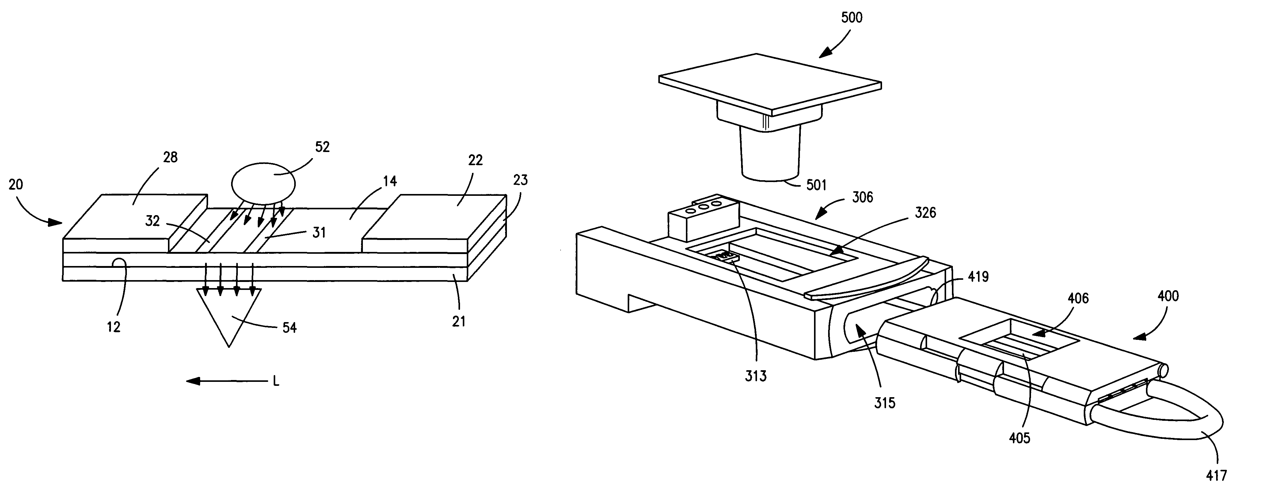
[0093]The ability to form an optical detection system in accordance with the present invention was demonstrated. The EL device was made by BKL, Inc. of Burr Ridge, Ill., and had a size of 60 millimeters×300 millimeters. In addition, the EL device also had an emission maxima of 525 nanometers to give “green” light emission. The EL device was powered by an AC power supply (ACM-500 from Behiman, Hauppauge, N.Y.) at 100 V and 400 Hz. The EL device was cut into 4 mm×60 mm strips that were inserted into an enclosure as shown in FIGS. 5-8 using spring-loaded contacts (70AD / Male / 4-up, Bourns, Riverside, Calif.) to make electrical contact through holes in the sample holder. The enclosure housed two blue-enhanced silicon photodiodes (PDB-V601, Photonic Detectors of Simi Valley, Calif.). The purpose of the enclosure was to optically isolate the system from the external environment and ensure proper alignment between the photodiodes and assay devices. The photodiodes were positioned so that the...


PUM

PropertyMeasurementUnit
thicknessaaaaaaaaaa
thicknessaaaaaaaaaa
lengthaaaaaaaaaa

Abstract

A system that employs transmission-based detection techniques to determine the presence or concentration of an analyte within a test sample is provided. Specifically, the optical detection system contains a chromatographic-based assay device that is positioned in the electromagnetic radiation path defined between an illumination source and detector. To enhance the sensitivity and signal-to-noise ratio of the system without significantly increasing costs, the distance between the illumination source and / or detector and the assay device is minimized. The illumination source and / or detector may also be positioned directly adjacent to the assay device. In addition, the system may be selectively controlled to reduce reliance on external optical components, such as optical filters or diffusers.

Description

RELATED APPLICATIONS[0001]The present application claims priority to a provisional application having Ser. No. 60 / 608,941, which was filed on Apr. 30, 2004.BACKGROUND OF THE INVENTION[0002]Optical detection systems are often utilized to qualitatively, quantitatively, or semi-quantitatively determine the presence or concentration of an analyte within a test sample. Unfortunately, conventional optical detection systems generally suffer from at least one of two major problems. One problem is that the optical detection system, although sensitive and accurate, is too expensive and complex for use by ordinary consumers, such as non-technical personnel at doctor's offices, clinics, home, rest homes, etc. To reduce cost and complexity, other optical detection systems have thus been developed. However, such systems typically achieve a reduction in cost and complexity through a concurrent loss in sensitivity. Although such a loss in sensitivity is not necessarily critical in all applications,...

Claims


Application Information

Patent Timeline
Patent Type & Authority Patents(United States)
IPC IPC(8): G01N21/00G01N33/52G01N33/543G01N33/558
CPCG01N33/521G01N33/54386G01N33/558G01N21/00G01N33/54388
Inventor COHEN, DAVID SAMUELSONG, XUEDONGKNOTTS, MICHAELFEASTER, SHAWN RAYATANASSOV, ZDRAVKO SAVOV
Owner KIMBERLY-CLARK WORLDWIDE INC
Why Eureka
Try Eureka