
Channel equalizer and method of processing broadcast signal in receiving system

a technology of receiving system and equalizer, which is applied in the field of digital telecommunications system, can solve the problems of data quality that is to be reduced, and data that is to be transmitted should have a low error ratio, so as to achieve the effect of enhancing channel equalization performan

Inactive Publication Date: 2010-09-14
LG ELECTRONICS INC
View PDF4 Cites 52 Cited by
  • Summary
  • Abstract
  • Description
  • Claims
  • Application Information

AI Technical Summary

Benefits of technology

The solution significantly enhances the receiving performance of supplemental data by improving resistance to noise and interference, ensuring compatibility with existing broadcast systems and maintaining data integrity even in poor channel conditions.

Problems solved by technology

However, when used indoors, the intensity of the signals may decrease due to a blockage caused by the walls or disturbance caused by approaching or proximate mobile objects.
Accordingly, the quality of the received digital signals may be deteriorated due to a ghost effect and noise caused by reflected waves.
However, unlike the general video / audio data, when transmitting the supplemental data, the data that is to be transmitted should have a low error ratio.
Conversely, in case of the supplemental data (e.g., program execution file, stock information, etc.), an error even in a single bit may cause a serious problem.
Furthermore, in a poor channel environment, the receiving performance of the conventional receiving system may be deteriorated.

Method used


Image

  • Channel equalizer and method of processing broadcast signal in receiving system
  • Channel equalizer and method of processing broadcast signal in receiving system
  • Channel equalizer and method of processing broadcast signal in receiving system

Examples


first embodiment

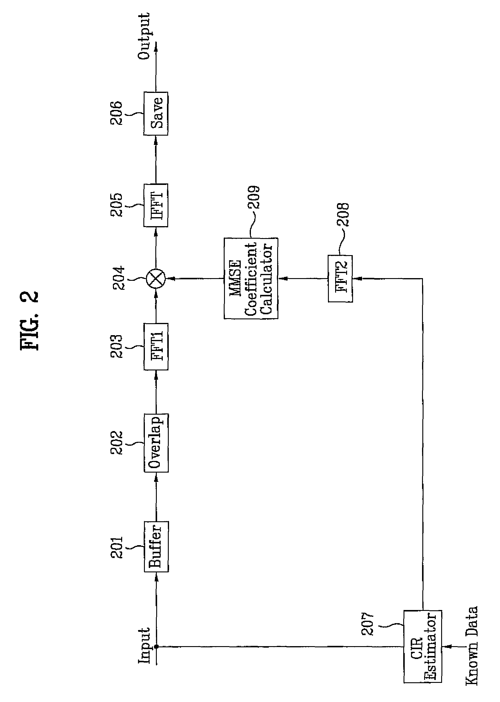
[0033]The first embodiment of the present invention relates to directly copying the CIR estimated from the body area and using the copied CIR for the channel equalization process in the head / tail areas. More specifically, when the head / tail areas and the body area are assumed to be similar to one another due to non-frequent channel change based upon a predetermined time interval, the CIR of the body area may be directly used (i.e., without modification) in the head / tail areas adjacent to the corresponding body area. For example, in order to perform the channel equalization process in the head area, the CIR estimated from the body area adjacent to the corresponding head area may be used. And, in order to perform the channel equalization process in the tail area, the CIR estimated from the body area adjacent to the corresponding tail area may be used.

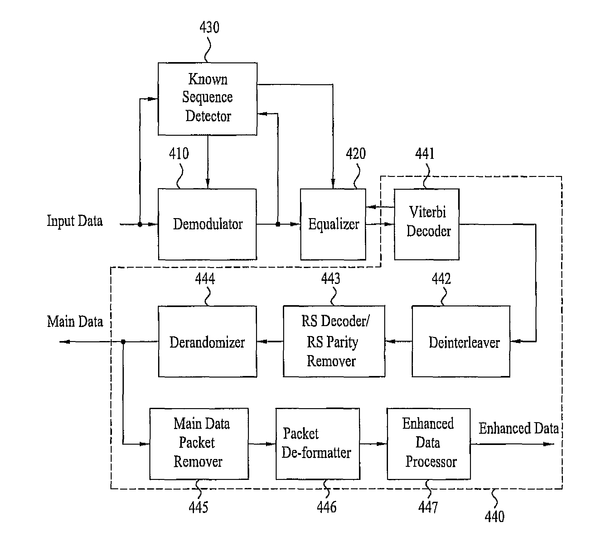
[0034]FIG. 2 illustrates a block diagram showing an example of the channel equalizer using such method (or such CIR) according to the fi...

second embodiment

[0038]The second embodiment of the present invention relates to performing extrapolation on the CIR of the body area so as to use the extrapolated CIR for the channel equalization of the head / tail areas. Herein, when a value F(A) of a function F(x) at a particular point A and a value F(B) of the function F(x) at another particular point B are known, an extrapolation refers to estimating a function value of a point outside of the section between points A and B.

[0039]FIG. 3 illustrates an example of an extrapolation operation. Particularly, FIG. 3 illustrates the simplest form of linear extrapolation among a wide range of extrapolation operations. More specifically, since the values F(A) and F(B) each from points A and B, respectively, are known, a straight line passing between the A-B section may be obtained so as to calculate an approximate value {circumflex over (F)}(C) of the F(x) function at point C. Herein, the equation of the straight line passing the coordinates (A,F(A)) and (...

third embodiment

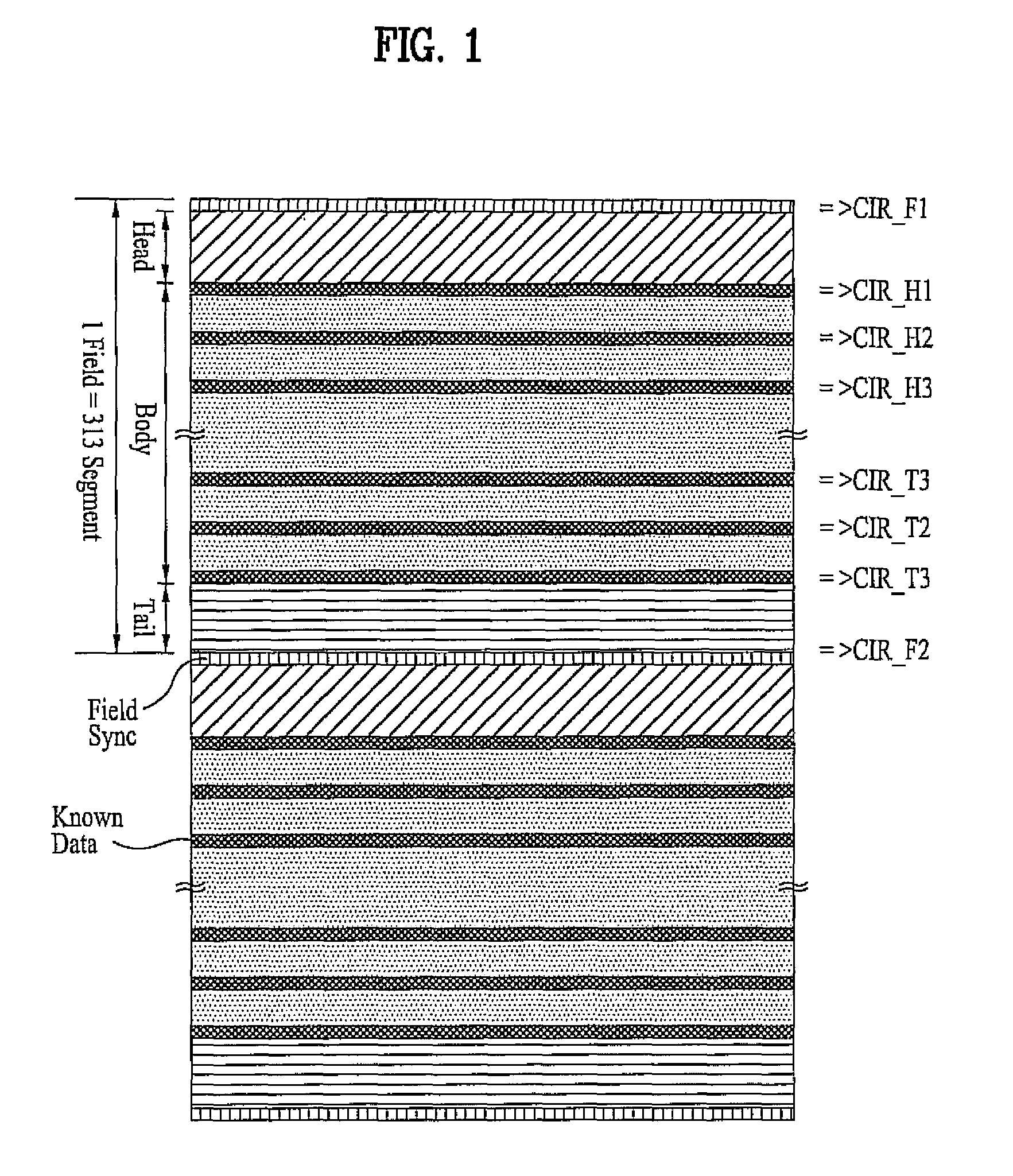
[0052]The third embodiment of the present invention relates to performing interpolation on the CIR of the body area and the CIR estimated by using field synchronization data so as to estimate a CIR, which is then used to perform channel equalization of the head / tail areas. More specifically, as shown in FIG. 1, a set of field synchronization data for synchronization recovery of a frame having the length of a segment is included in each field of the transmitted frame, which is transmitted from the transmitting system. In the present invention, the field synchronization data may be used to calculate the CIR. Then, interpolation is performed on the CIR obtained from the body area and the CIR obtained from the field synchronization section, thereby enabling the CIR of the head / tails area to be estimated. Herein, when a value F(A) of a function F(x) at a particular point A and a value F(B) of the function F(x) at another particular point B are known, an interpolation refers to estimating...


PUM


Abstract

A channel equalizer includes an overlap unit, an estimator, a calculator, a compensator, and a save unit. The overlap unit overlaps a group of data packets in a broadcast signal. The group data packets include a head, a body, and a tail, and a known data sequence is periodically included in the body. The estimator estimates a CIR of each data region the body using the known data sequence, and it further estimates CIRs of data regions in the head or tail using the CIRs obtained for the data regions in the body. The calculator calculates equalization coefficients based on the CIRs estimated by the estimator, and the compensator compensates channel distortion of the overlapped data using the equalization coefficients. The save unit saves the compensated data.

Description

[0001]This application claims the benefit of the Korean Patent Application No. 10-2006-0020140, filed on Mar. 02, 2006, which is hereby incorporated by reference as if fully set forth herein. Also, this application claims the benefit of the Korean Patent Application No. 10-2006-0089736, filed on Sep. 15, 2006, which is hereby incorporated by reference as if fully set forth herein. This application also claims the benefit of U.S. Provisional Application No. 60 / 883,500, filed on Jan.4, 2007, which is hereby incorporated by reference.BACKGROUND OF THE INVENTION[0002]1. Field of the Invention[0003]The present invention relates to a digital telecommunications system, and more particularly, to a channel equalizer and a method of processing broadcast signal in a receiving system. Although the present invention is suitable for a wide scope of applications, it is particularly suitable for receiving digital broadcast signal.[0004]2. Discussion of the Related Art[0005]Presently, the technology...

Claims


Application Information

Patent Timeline
Patent Type & Authority Patents(United States)
IPC IPC(8): H04K1/10H04L27/28H04L27/00
CPCH04L1/0047H04L1/0057H04L1/0059H04L1/0065H04L1/007H04L1/0071H04L25/022H04L25/03159H04N7/163H04N21/235H04N21/2383H04N21/4345H04N21/435H04N21/4382H04N21/4623H04L1/0054H04L2001/0093H04L2025/03522
Inventor KIM, BYOUNG GILLCHOI, IN HWANKWAK, KOOK YEON
Owner LG ELECTRONICS INC
Learn More