
Exhaust turbo supercharger

a turbocharger and exhaust gas technology, applied in the direction of threaded fasteners, liquid fuel engines, screw heads, etc., can solve the problem of high temperature of the bolt, achieve the effect of reducing the inner pressure, ensuring the sealing capacity of the gasket, and reducing the pressure applied by the exhaust gas to the gask

Active Publication Date: 2010-09-21
MITSUBISHI HEAVY IND LTD
View PDF18 Cites 33 Cited by
  • Summary
  • Abstract
  • Description
  • Claims
  • Application Information

AI Technical Summary

Benefits of technology

The present invention provides an exhaust turbo supercharger that can effectively prevent exhaust gas leakage and has improved workability in assembly and disassembly. This is achieved by using a bolt with an internal thread insert made from a heat insulating material, which prevents heat transmission between the turbine housing and the bolt. The bolt engages with a bearing housing and a gasket, which seals the area between the turbine housing and the bearing housing. The bolt is set to a lower temperature than the turbine housing, reducing the likelihood of a reduction in fastening force and ensuring the contact pressure of the gasket is maintained. The invention also provides an exhaust turbo supercharger with a through hole in the turbine housing and a nut that engages with the bolt, further preventing heat transmission between the turbine housing and the bolt.

Problems solved by technology

Moreover, since the thread face of the bolt that engages with the screw hole of the turbine housing is in surface contact with the turbine housing, the temperature of this bolt becomes high.

Method used


Image

  • Exhaust turbo supercharger
  • Exhaust turbo supercharger
  • Exhaust turbo supercharger

Examples


first embodiment

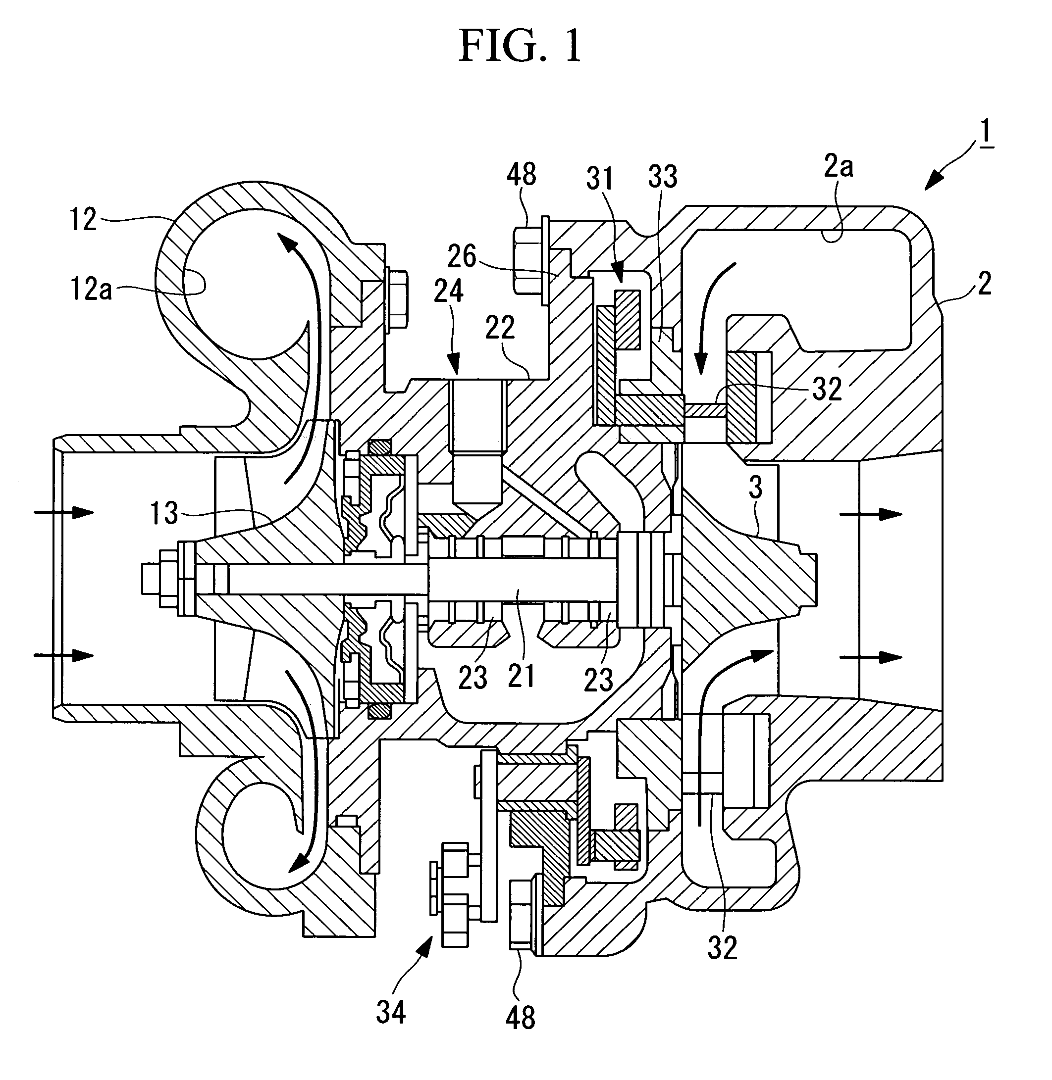
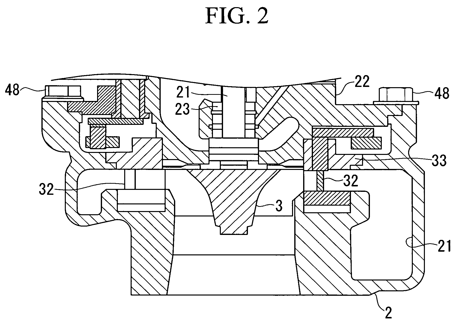
[0107]Hereunder, a first embodiment of the present invention is described, with reference to FIG. 1 and FIG. 2. In the present embodiment, an example in which the present invention is applied to a VG exhaust turbo supercharger is described. The present invention is not limited to this example and may be applied to a generic exhaust turbo supercharger.

[0108]As shown in the vertical sectional view of FIG. 1, an exhaust turbo supercharger 1 according to the present embodiment has a turbine housing 2 inside of which there is formed a spiral flow passage 2a, and a turbine wheel 3, which is provided in a substantially radial direction center section of this turbine housing 2. Into the spiral flow passage 2a of the turbine housing 2, exhaust gas from an internal combustion engine (not shown in the drawing) is supplied. The turbine wheel 3 is rotation driven by exhaust gas supplied into this spiral flow passage 2a. Here, material of the turbine wheel is generic heat resistant alloy.

[0109]Mo...

second embodiment

[0132]Next, a second embodiment of the present invention is described, with reference to FIG. 4.

[0133]An exhaust turbo supercharger 51 according to the present embodiment is an exhaust turbo supercharger shown in the first embodiment, in which the structure for connecting the turbine housing 2 and the bearing housing 22 has been modified. Hereunder, the same reference symbols are assigned to constructions similar to, or the same as, those in the first embodiment, and detailed descriptions thereof are omitted.

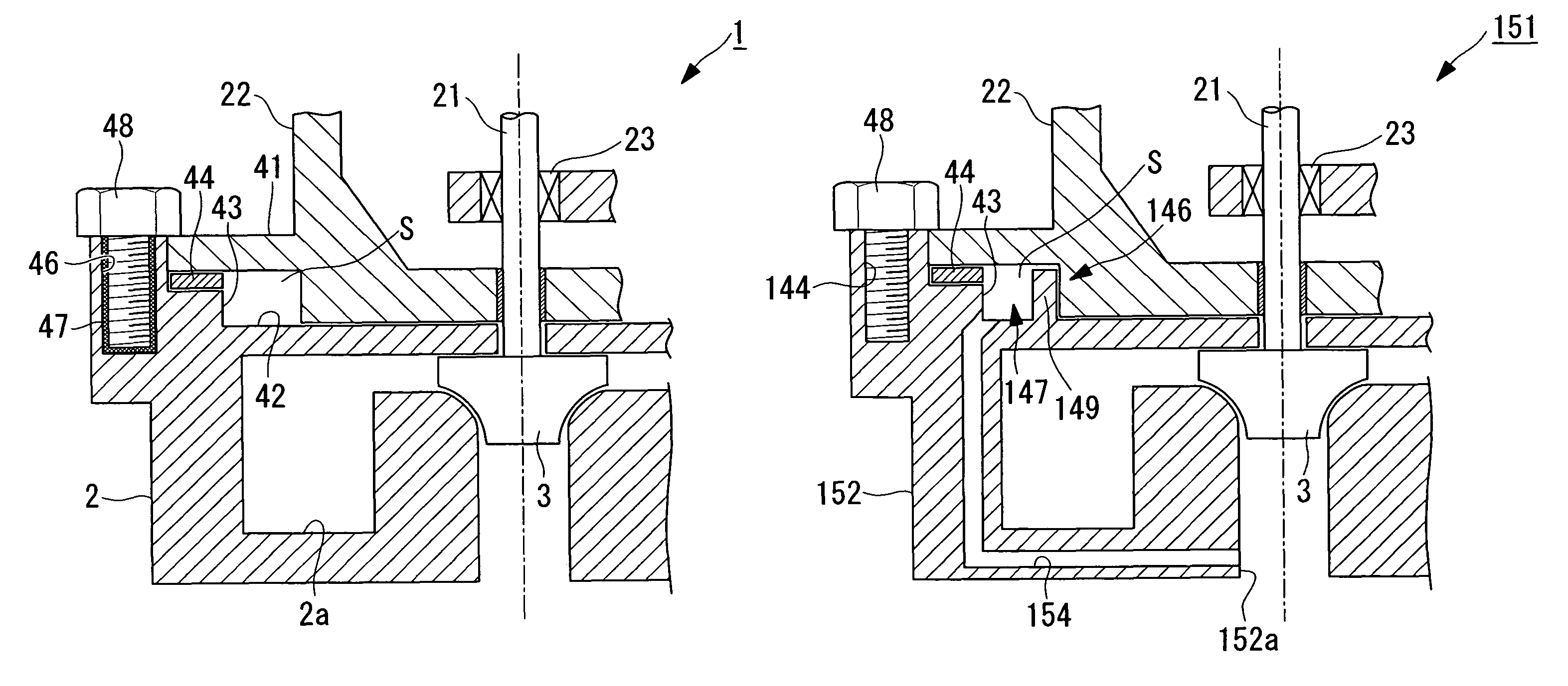
[0134]In this exhaust turbo supercharger 51, a turbine housing 52 is used instead of the turbo housing 2. The turbine housing 52 is a turbine housing 2 as shown in the first embodiment, in which, instead of the blind bolt insert hole 46, there is provided a through hole 56 through which the bolt 48 is inserted.

[0135]In this exhaust turbo supercharger 51, by inserting the bolt 48 through the through hole 56 of the turbine housing 52 and engaging the nut 57 with the tip end of the...

third embodiment

[0141]Next, a third embodiment of the present invention is described, with reference to FIG. 5 and FIG. 6.

[0142]An exhaust turbo supercharger 61 according to the present embodiment is characterized mainly in that a turbine housing 62 is used instead of the turbine housing 2 in the exhaust turbo supercharger 1 as shown in the first embodiment. Hereunder, the same reference symbols are assigned to constructions similar to, or the same as, those in the first embodiment, and detailed descriptions thereof are omitted.

[0143]The turbine housing 62 is a turbine housing 2 as shown in the first embodiment in which, instead of the bolt insert hole 46, there is provided a screw hole 66 with which the bolt 48 is engaged. Moreover, in the turbine housing 62, heat radiating fins 67 are provided in the vicinity of the screw hole 66. In the present embodiment, as shown in FIG. 6, in the turbine housing 62, an area in which the screw hole 66 is formed has a shape that projects toward the outer periph...


PUM


Abstract

An exhaust turbo supercharger is provided that is able to effectively prevent exhaust gas that has flowed into between a turbine housing and a bearing housing from leaking to outside of the device, while allowing an excellent level of workability in assembly and disassembly. Included is a turbine housing, into which exhaust gas from an internal combustion engine is introduced; a turbine wheel which is provided within the turbine housing and which is rotation-driven by the exhaust gas; a turbine shaft, one end of which is inserted into the turbine housing, and to which the turbine wheel is attached; a bearing which supports the turbine shaft; and a bearing housing which is connected to the turbine housing and inside of which the bearing is housed. A bolt insert hole is formed in the turbine housing, and an internal thread insert made from a heat insulating material is provided in the bolt insert hole, and the turbine housing and the bearing housing are fixed by a bolt that engages with the internal thread insert.

Description

BACKGROUND OF THE INVENTION[0001]I. Technical Field[0002]The present invention relates to an exhaust turbo supercharger to be used in an internal combustion engine that serves as a power source in a vessel, motor vehicle or power generator, in particular, to a VG (variable geometry) type exhaust turbo supercharger.[0003]II. Description of the Related Art[0004]An exhaust turbo supercharger improves the combustion efficiency of an internal combustion engine by forcefully supplying air into a combustion chamber of the internal combustion engine to improve the output of the internal combustion engine and improve the properties of exhaust gas of the internal combustion engine.[0005]As such an exhaust turbo supercharger, a variable displacement type exhaust turbo supercharger disclosed in Japanese Unexamined Patent Application, Publication No. 2004-156592 is known for example.[0006]This variable displacement type exhaust turbo supercharger has a turbine housing (turbine casing), inside of...

Claims


Application Information

Patent Timeline
Patent Type & Authority Patents(United States)
IPC IPC(8): F02D23/00F16B35/04F16B39/04F01D25/24F02B39/00
CPCF01D25/16F01D25/24F02B39/00F02C6/12F02C7/24F05B2260/301F05D2220/40F05D2300/502F02B39/14F02B37/22
Inventor HAYASHI, NORIYUKIJINNAI, YASUAKIIBARAKI, SEIICHITAKAHASHI, FUMIHARUAKIYAMA, YOH
Owner MITSUBISHI HEAVY IND LTD
Learn More