Controllable multi-band antenna device and portable radio communication device comprising such an antenna device

a multi-band antenna and portable radio technology, applied in the field of antenna devices, can solve the problems of limited number of frequency bands in passive antennas, affecting the operation of vehicles, and putting some constraints on the antenna configuration, so as to achieve the effect of maintaining rf performance, reducing antenna size, and improving bandwidth of the antenna device according to the invention

Active Publication Date: 2010-09-21
SAMSUNG ELECTRONICS CO LTD
View PDF13 Cites 35 Cited by
  • Summary
  • Abstract
  • Description
  • Claims
  • Application Information

AI Technical Summary

Benefits of technology

[0012]The invention provides an antenna device and a portable radio communication device wherein the problems in prior art devices are avoided or at least mitigated. Thus, there is provided a multi-band antenna device having an antenna volume as small as about 2 cm3 which means that the size of the antenna is remarkably reduced compared to standard multi-band patch antennas but still with maintained RF performance. Also, the bandwidths of the antenna device according to the invention can be improved compared to corresponding prior art devices but without any increase in size, which is believed to be a result of the use of the basic frequency mode of the antenna structure. As an example thereof, bandwidths of as much as 15% of the centre frequency of the higher frequency band have been obtained as compared to 9-10% in conventional prior art antenna devices.
[0013]The filter is preferably a low-pass filter, providing an efficient RF blocking arrangement. By providing the filter integral with the radiating element, better performance is obtained.

Problems solved by technology

However, the application of internal antennas in a mobile phone puts some constraints on the configuration of the antenna, such as the dimensions of the radiating element or elements, the exact location of feeding and grounding portions etc.
These constraints may make it difficult to find a configuration of the antenna that provides a wide operating frequency band.
The number of frequency bands in passive antennas is limited by the size of the antenna.
Although this provides for a frequency control, the antenna device still has a large size and is not well adapted for switching between two or more relatively spaced apart frequency bands, such as between the GSM and DCS / PCS bands.
A problem in prior art antenna devices is thus to provide a multi-band antenna with a small size and volume and broad frequency bands which retains good performance.

Method used


Image

  • Controllable multi-band antenna device and portable radio communication device comprising such an antenna device
  • Controllable multi-band antenna device and portable radio communication device comprising such an antenna device
  • Controllable multi-band antenna device and portable radio communication device comprising such an antenna device

Examples


Embodiment Construction

[0028]In the following, a detailed description of preferred embodiments of an antenna device according to the invention will be given. In the description, for purposes of explanation and not limitation, specific details are set forth, such as particular hardware, applications, techniques etc. in order to provide a thorough understanding of the present invention. However, it will be apparent to one skilled in the art that the present invention may be utilized in other embodiments that depart from these specific details. In other instances, detailed descriptions of well-known methods, apparatuses, and circuits are omitted so as not to obscure the description of the present invention with unnecessary details.

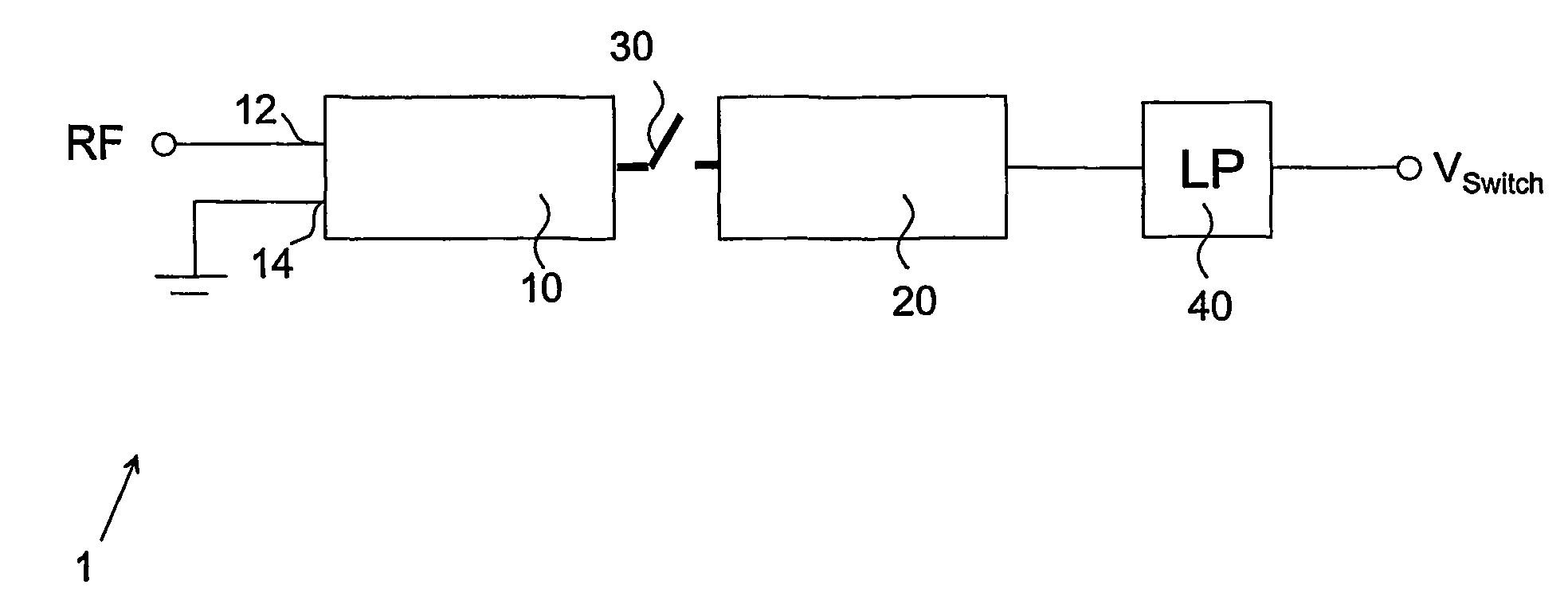
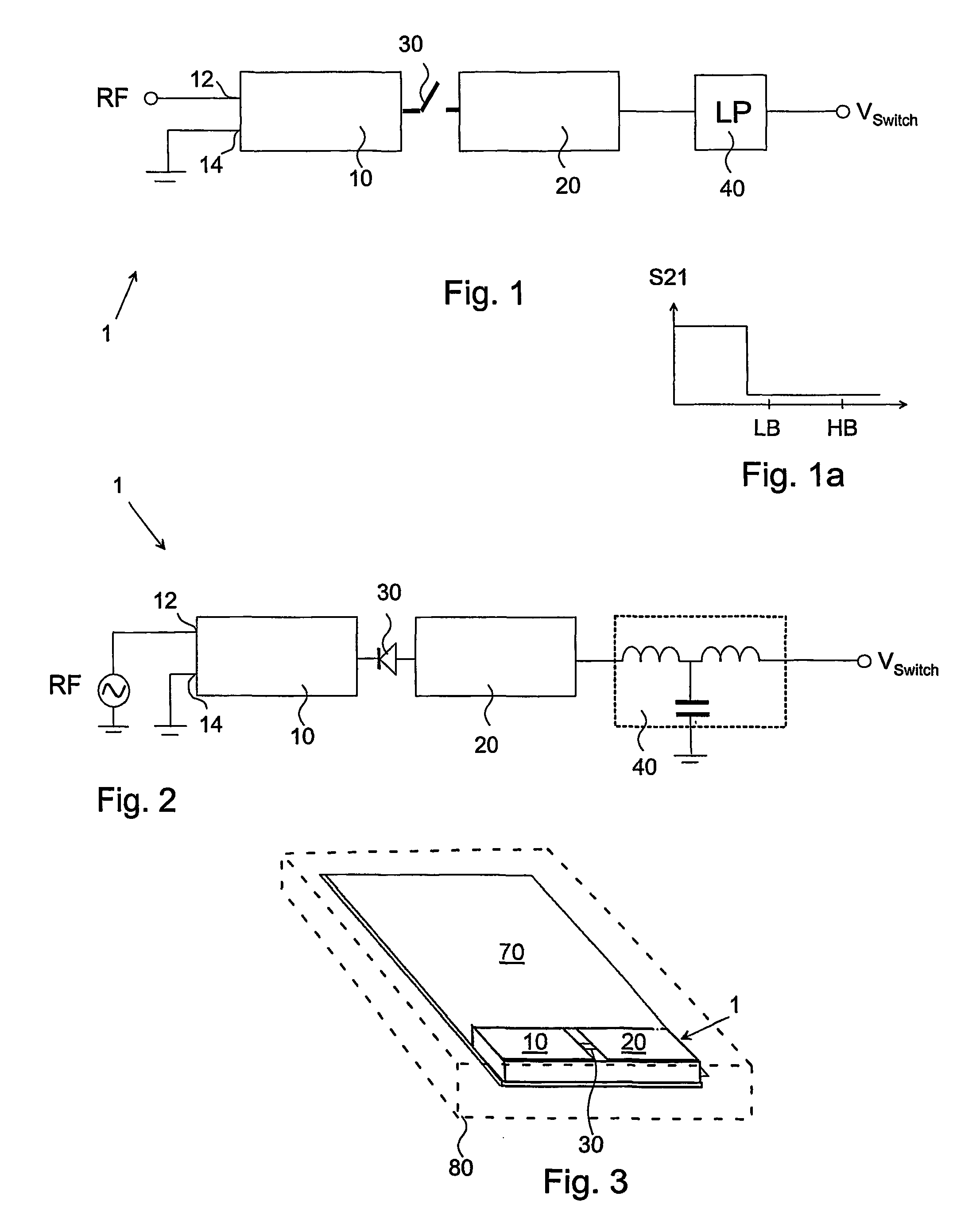
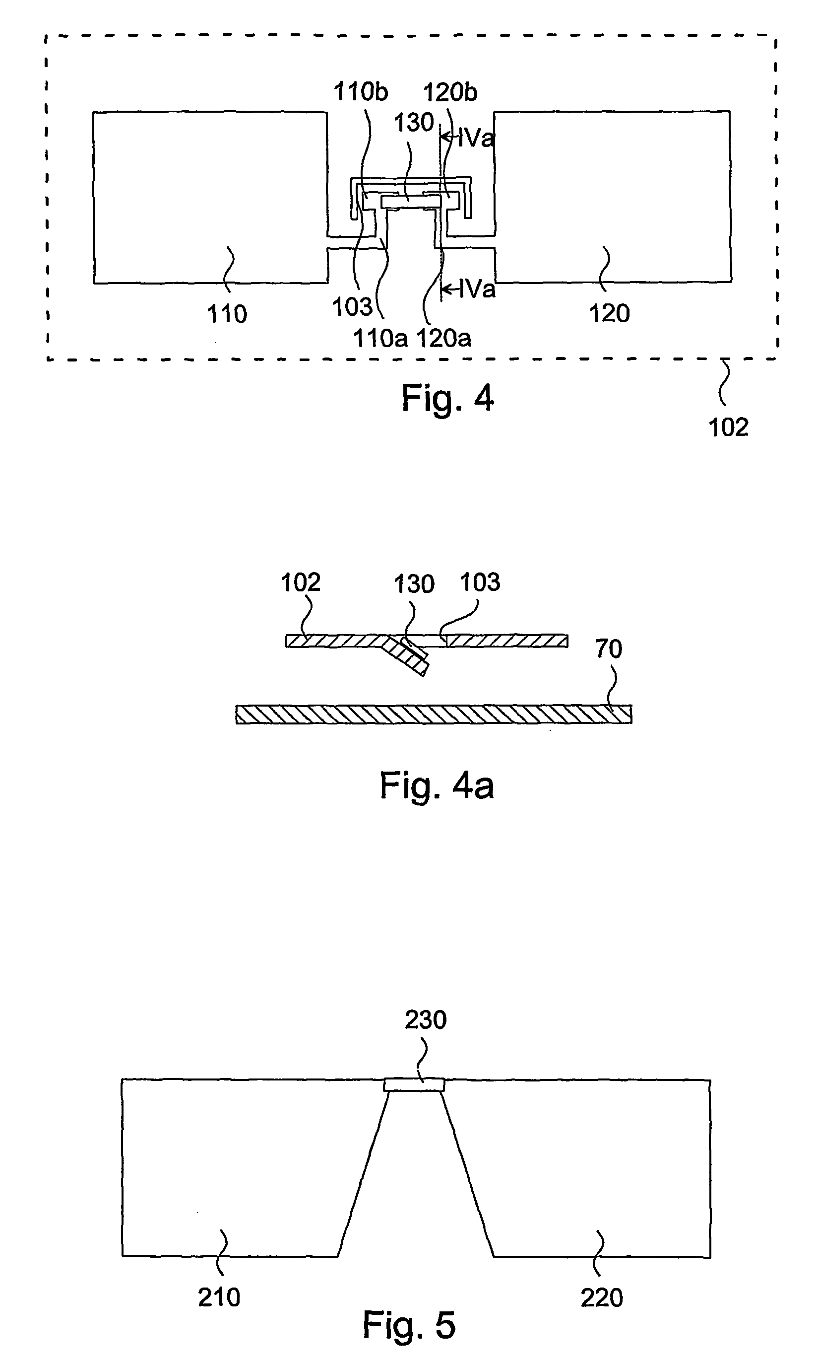
[0029]In FIG. 1, there is shown an antenna device, generally designated 1. The antenna device comprises a first generally planar rectangular radiating element 10 made of an electrically conductive material, such as a sheet metal or a flex film, as is conventional. A source RF of ra...


PUM


Abstract

A multi-band antenna device for a portable radio communication device has first and second radiating elements (10, 20′). A controllable switch (30) is arranged between the radiating elements for selectively interconnecting and disconnecting thereof. The state of the switch is controlled by means of a control voltage input (VSwitch). A filter (40) comprising a pure resistance that blocks radio frequency signals is arranged between the second radiating element and the control voltage input. By means of this arrangement, two broad and spaced apart frequency bands are obtained with retained performance and small overall size of the antenna device. A communication device comprising such an antenna device is also provided.

Description

FIELD OF INVENTION[0001]The present invention relates generally to antenna devices and more particularly to a controllable internal multi-band antenna device for use in portable radio communication devices, such as in mobile phones. The invention also relates to a portable radio communication device comprising such an antenna device.BACKGROUND[0002]Internal antennas have been used for some time in portable radio communication devices. There are a number of advantages connected with using internal antennas, of which can be mentioned that they are small and light, making them suitable for applications wherein size and weight are of importance, such as in mobile phones.[0003]However, the application of internal antennas in a mobile phone puts some constraints on the configuration of the antenna, such as the dimensions of the radiating element or elements, the exact location of feeding and grounding portions etc. These constraints may make it difficult to find a configuration of the ant...

Claims


Application Information

Patent Timeline
Patent Type & Authority Patents(United States)
IPC IPC(8): H01Q1/24H01Q1/38H01Q3/24H01Q1/27H01Q19/00
CPCH01Q3/247H01Q19/005B61G11/00B61G11/10B61D15/06B60R19/02B60R19/023F16F7/00B60Y2200/30
Inventor THORNELL-PERS, ANDERS
Owner SAMSUNG ELECTRONICS CO LTD
Why Eureka
Try Eureka