Retractable ramp

a step or ramp technology, applied in the direction of bridges, transportation items, refuse gathering, etc., can solve the problems of horizontal gap between passenger railcars and high-level platforms, and difficulty in providing suitable access to all passengers, etc., to achieve the effect of quick and inexpensive retrofitting

Inactive Publication Date: 2010-09-28
LINC DESIGN +2
View PDF63 Cites 18 Cited by
  • Summary
  • Abstract
  • Description
  • Claims
  • Application Information

AI Technical Summary

Benefits of technology

[0013]Therefore, an object of the present invention is to provide a ramp assembly that has a low-profile while providing access to either of the doors on opposite sides of a railcar. Additionally, it is another object of the present invention to provide such a ramp assembly that can be quickly and inexpensively retrofitted into an existing railcar.
[0018]The first locking member and the second locking member may be substantially wedge-shaped thereby providing a smooth transition between a surface and the first and second ramp sections. The first locking member and the second locking member may be locked and unlocked manually, mechanically, electronically, pneumatically or any combination thereof.
[0021]The ramp assembly may further include a plurality of floor plates for covering the first sectional ramp and the second sectional ramp when the first and second sectional ramps are stored. The first end of the first sectional ramp and the first end of the second sectional ramp may be coupled together by a first locking member and the second end of the first sectional ramp and the second end of the second sectional ramp may be coupled together by a second locking member. The first locking member and the second locking member may be substantially wedge-shaped thereby providing a smooth transition between a surface and the first and second ramp sections. The first locking member and the second locking member may be locked and unlocked manually, mechanically, electronically, pneumatically or any combination thereof.

Problems solved by technology

Commuter rail systems, in particular, have difficulty providing suitable access to all passengers, including the elderly and passengers with mobility limitations due to variable horizontal and vertical gaps between the railcars and passenger boarding platforms.
Many commuter rail systems share rail platforms with freight trains, and freight car bodies are generally wider than the bodies of passenger railcars, resulting in a horizontal gap between passenger railcars and high-level platforms.
Also, many train stations are built along a curved track, which causes variation in a horizontal gap between the platform and railcar.
Then the tracks are lowered on top of a higher bed thereby raising the railcar floor to ground level and causing a larger vertical gap.
Presently, available step or ramp devices are solely used for wheelchair access or are not capable of automatically or manually bridging varying horizontal and vertical gaps of the magnitude found in current commuter rail systems (including those that share tracks with freight trains) and complying with the requirements of government regulations for bridging such gaps.
Most such devices are about 29 inches wide and about 32 inches long, which means that to meet governmental requirements for ramp angles, the bridge plate cannot be used for vertical gaps that are higher than 4 inches.
Using a bridge plate on a gap that is 6 inches high can be difficult and risky for people who independently drive their wheelchair onto a railcar.
Also, using a manual bridge plate is time consuming and increases the potential for rail delays.
Automatic wheelchair lift-type mechanisms have also been used but are complex and take up valuable railcar boarding space.
However, each of these ramp systems suffers from various deficiencies.
For instance, none of the prior art systems provides for a ramp system that can be positioned on the floor of a railcar and has a low-profile to avoid interference with passenger traffic entering and exiting the railcar.

Method used


Image

  • Retractable ramp
  • Retractable ramp
  • Retractable ramp

Examples


Embodiment Construction

[0038]For purposes of the description hereinafter, the terms “upper”, “lower”, “right”, “left”, “vertical”, “horizontal”, “top”, “bottom”, “lateral”, “longitudinal” and derivatives thereof shall relate to the invention as it is oriented in the drawing figures. However, it is to be understood that the invention may assume various alternative variations, except where expressly specified to the contrary. It is also to be understood that the specific devices illustrated in the attached drawings, and described in the following specification, are simply exemplary embodiments of the invention. Hence, specific dimensions and other physical characteristics related to the embodiments disclosed herein are not to be considered as limiting.

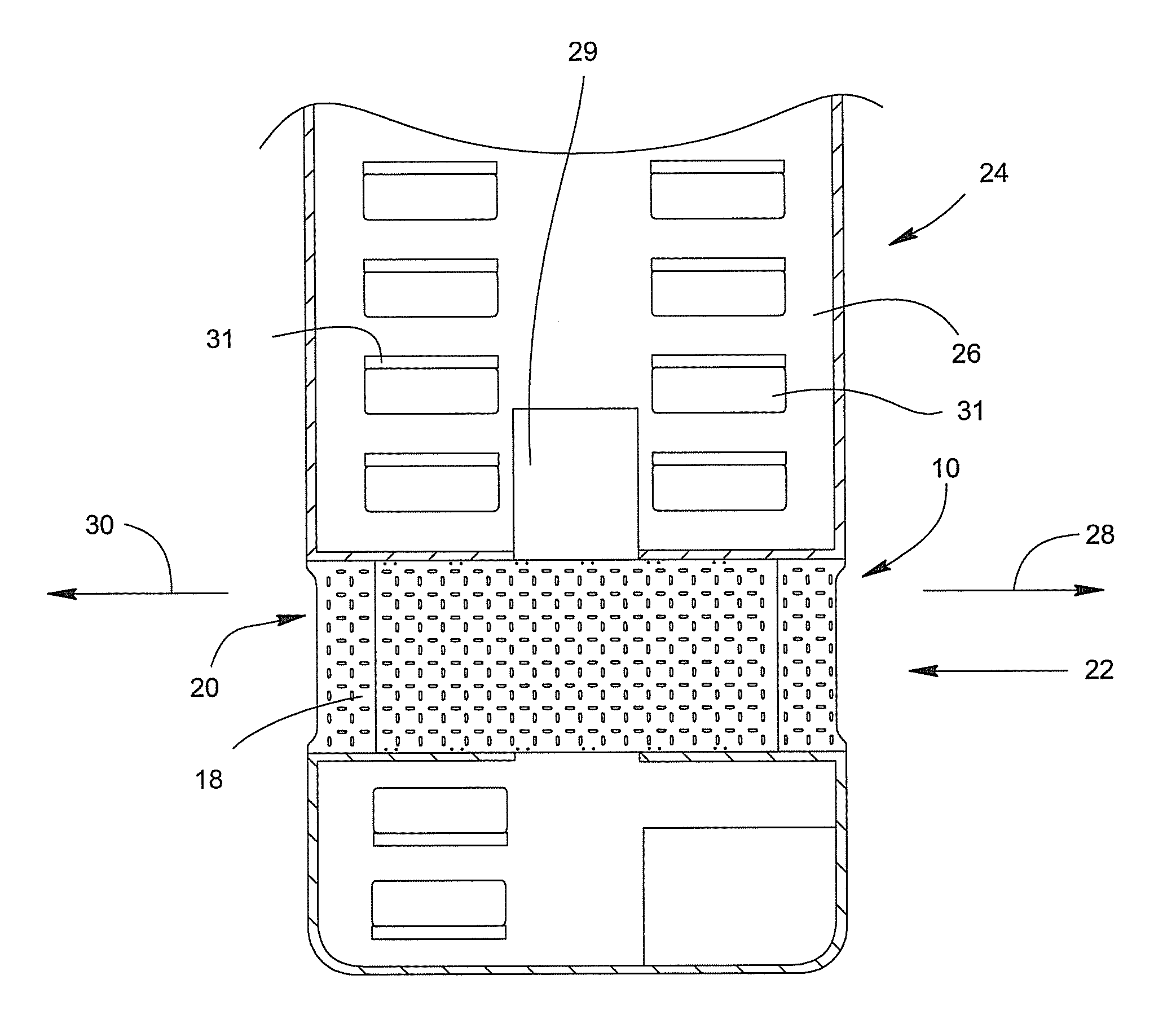
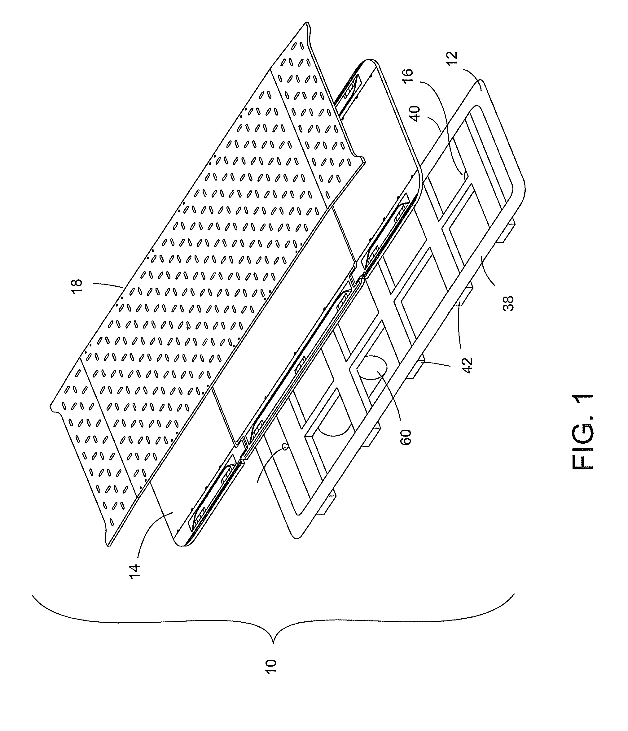
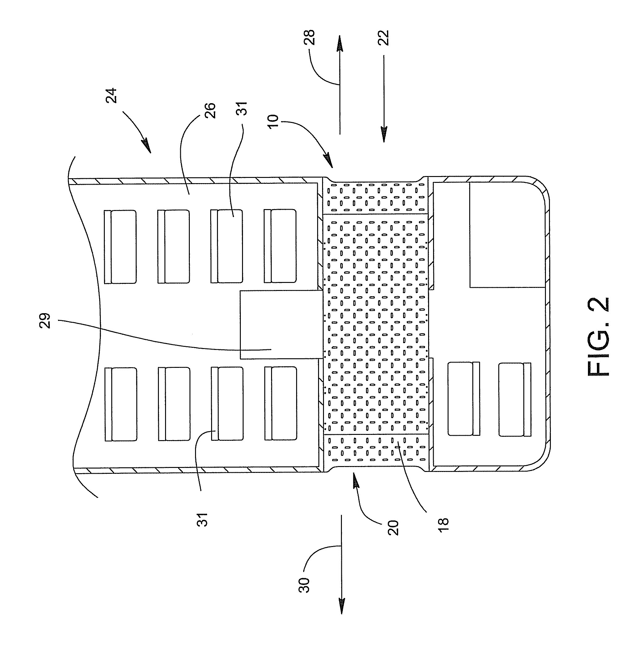
[0039]With reference to FIG. 1, a ramp assembly, denoted generally as reference numeral 10, includes an optional frame structure 12, a sectional ramp 14 and a drive mechanism 60. Sectional ramp 14 may be covered with a floorplate structure having a sectional f...


PUM

PropertyMeasurementUnit
lengthaaaaaaaaaa
heightaaaaaaaaaa
heightaaaaaaaaaa

Abstract

A ramp assembly includes an elongated frame sized and shaped to extend between a first door and a second door aligned opposite each other on opposed sides of a vehicle; a first sectional ramp section having a first end and a second end; and a second sectional ramp having a first end and a second end. The first sectional ramp is slidably moveable along the frame from a stored position to a deployed position on either of the opposed sides of the vehicle. The second sectional ramp is positioned adjacent the first sectional ramp and is slidably moveable along the frame from a stored position to a deployed position on either of the opposed sides of the vehicle. The ramp assembly also includes a first locking mechanism coupled to the first end of each of the first sectional ramp and the second sectional ramp; and a second locking mechanism coupled to the second end of each of the first sectional ramp and the second sectional ramp. The first locking mechanism is placed in a locked position and the second locking mechanism is placed in an unlocked position to allow the first and second sectional ramps to be coupled together and moved from the stored position to the deployed position through the first door. The second locking mechanism is placed in a locked position and the first locking mechanism is placed in an unlocked position to allow the first and second sectional ramps to be coupled together and moved from the stored position to the deployed position through the second door.

Description

STATEMENT REGARDING FEDERALLY SPONSORED RESEARCH[0001]This invention was made with government support under Department of Education PR / Award No. H133S050136 awarded by the Department of Education. The government has certain rights in this invention.BACKGROUND OF THE INVENTION[0002]1. Field of the Invention[0003]The disclosure contained in this document relates to a retractable step or ramp that is automatically or manually extensible from the floor of a railcar or other means of transportation for the boarding and exit of passengers, and particularly to a retractable step portion or ramp portion that is selectively extensible outwardly from either side of the railcar or other vehicle to enable boarding and exit of passengers through either door on opposed sides of the railcar or other vehicle.[0004]2. Description of Related Art[0005]There is a need for ambulatory people and those unable to climb up steps to be able to gain access to public transportation systems for employment, educ...

Claims


Application Information

Patent Timeline
Patent Type & Authority Patents(United States)
IPC IPC(8): E01D19/00
CPCA61G3/061E04F11/002Y10T29/49716E04F2011/005A61G2003/067A61G3/067
Inventor VAN ROOSMALEN, LINDAGLOGOWSKI, FRANCIS S.HEINER, DAVID A.JAMISON, III, ROBERT S.HORVATH, PETER D.WALKER, STEVEN
Owner LINC DESIGN
Why Eureka
Try Eureka