
Panel joining member

a joining member and panel technology, applied in the field of joining members, can solve the problems of less efficient sealing of the joint between the panel and extrusion, less stress on the screw tightening, and less stress on the panel, so as to achieve the effect of facilitating the introduction of the joining member and reducing the stress on the panel

Inactive Publication Date: 2010-09-28
QUENTOR
View PDF50 Cites 29 Cited by
  • Summary
  • Abstract
  • Description
  • Claims
  • Application Information

AI Technical Summary

Benefits of technology

"The invention provides a method for easily connecting panels to a joining member by inserting a fastener through a recess in the panel and engaging it with a fastener receiver in the joining member. The recess is formed adjacent to the edge of the panel and the fastener is inserted at an angle to reduce stress on the panel. The fastener can be an expanding rivet fastener or a screw thread fastener. The joining member has spaced opposed walls with a stop member to align the panel. The method minimizes stress on the panel and allows for rapid assembly with unskilled labor. The invention also provides a panel joining member with a recess and a fastener receiver for easy connection of panels. The recess narrows away from its open end to prevent vibration transmission and the fastener can be an adapter or a screw. The technical effects of the invention include improved strength of the joint, reduced vibration transmission, and easy assembly of panels."

Problems solved by technology

Firstly, the stress from tightening the screw is concentrated on the outer wall of the extrusion and panel skin.
Where, for example, the panels form part of a piece of luggage or cladding on a building, then the sealing joint between the panel and extrusion will be less efficient and the exterior appearance of the joint will not be so pleasing.

Method used


Image

  • Panel joining member
  • Panel joining member
  • Panel joining member

Examples


Embodiment Construction

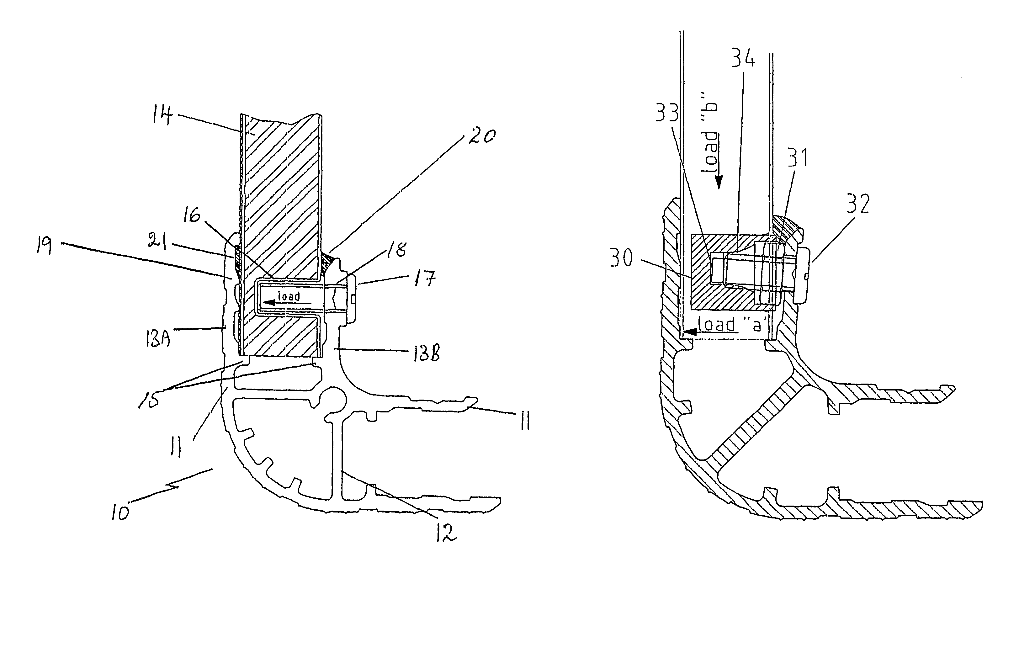
[0045]Referring initially to FIG. 1, this shows a first embodiment of a coupling means for securing panels together to form an article. The panels can be used in the construction of containers such as hand-portable cases or those which are to contain larger loads to be transported on lorries or ships. The containers are of modular construction and can be easily assembled either by the panel manufacturer or at a separate production site. Alternatively, panels can be joined together to form, for example, a partition wall.

[0046]The coupling means shown in FIG. 1 comprises a joining element 10. The joining element 10 can be formed from an extruded plastics material having good impact and scuff resistance or a metal (such as extruded aluminium). Two panel retaining portions 11 of the joining element 10 are at right angles to each other and separated by strengthening walls 12. Joining elements can be produced however with retaining portions at other desired angles, for example 180°. Each ...


PUM


Abstract

A method of connecting a panel (50) to a panel joining member (51) is disclosed. The method includes the steps of forming a recess (16) adjacent to an edge of a panel. The panel (50) is located within a panel joining member (51) the panel (50) being located against a stop member (15) and the recess (16) being aligned with an aperture (18) in the wall (13B) of the joining member (51). A fastener (17) is passed through the aperture (18) and urges the panel towards the outer wall (15) of the joining member (51). A receiver (30) is inserted into the recess (16) to assist engagement of the panel (50) with the fastener (17). The receiver (30) has a shape complementary to that of the recess (16). Opposing walls (13A, 13B) of the joining member (51) are inclined towards one another to improve panel retention. A push or snap-fit join is included to facilitate assembly.

Description

FIELD OF THE INVENTION[0001]The present invention relates to a joining member for holding together two or more panels. The invention further relates to a method of assembling said panels to construct, for example, structural or partition walls, flooring and roofing, furniture, containers or luggage.BACKGROUND OF THE INVENTION[0002]The assembly of large scale articles such as partition walls, furniture and transport containers by joining together smaller units, particularly panels, is well known in the art. Depending on the nature of the joint between adjacent units, articles of different strengths and function can be produced. For example, where a partition wall is to be formed, the individual units need to be retained in the desired orientation, but need not necessarily be required to be joined together in a robust fashion to withstand impacts.[0003]Where, however the units are to form part of a container, and particularly where the article is an item of luggage, the joints usually...

Claims


Application Information

Patent Timeline
Patent Type & Authority Patents(United States)
IPC IPC(8): E04B1/38A45C13/04E04B1/61F16B5/02F16B11/00F16B37/12
CPCF16B5/02F16B37/122F16B11/006A45C13/04E04B1/6116Y10T403/1683Y10T403/75
Inventor ASBURY, ANTHONY
Owner QUENTOR
Learn More