Floor panel with sealing means

a technology of floor panels and sealing means, which is applied in the direction of walls, building repairs, transportation and packaging, etc., can solve the problems of unsatisfactory cost and unsatisfactory known solutions to problems caused by moisture in connection with floor panels and floor materials

Inactive Publication Date: 2010-09-28
VÄLINGE INNOVATION AB
View PDF148 Cites 81 Cited by
  • Summary
  • Abstract
  • Description
  • Claims
  • Application Information

AI Technical Summary

Benefits of technology

[0046]The invention is based on the understanding that several types of seals may be involved for a moisture-proof locking system for floor panels which can be joined together, viz. “material seal” which counteracts swelling of joint edges, “material seal” and “joint seal” which counteract swelling and moisture penetration through the joint system, “compensation seal” which compensates for swelling and shrinkage of joint edges.
[0047]By “material seal” is meant a seal which prevents or counteracts spreading of moisture from the joint edge of a floor panel into the floor panel. By “joint seal” is meant a seal which prevents or counteracts migration of moisture through the joint along the joint surfaces. By “compensation seal” is meant a seal which adjusts to material movements caused by moisture in a floor panel (swelling and shrinkage) owing to changes of the moisture content, for instance by changes in relative humidity in the ambient air, and which counteracts stress under compression and the arising of a visible gap between the upper joint edges of neighboring floor panels owing to such material movements caused by moisture.
[0049]Therefore an object of the present invention is to eliminate or significantly reduce one or more of the remaining problems associated with moisture sealing in connection with manufacture and use of floor panels. A further object of the invention is to provide a rational and cost-efficient manufacturing method for manufacturing floor panel cores, floorboard elements, floorboards and floor panels.
[0055]Thus, according to the first, second and third aspects of the invention, the core can be provided with inserted and fixedly secured elastically deformable materials, which may act as a sealing means and / or as compensation means for swelling or shrinking of the floor panels. The elastically deformable materials are applied in portions that will later will be machined for making the connecting means of the completed floor panel. The elastically deformable material will thus be machined simultaneously as or in connection with the machining of the remaining parts of the joint system. As a result, the elastically deformable material can be made into accurately positioned and accurately dimensioned seals for forming the above-mentioned joint seals or compensation means.
[0058]By suitable methods, such as sawing or milling, the core can, before application of the surface layer (for instance a decorative surface layer), be pretreated so that, for instance, one or more grooves are formed in the surface in the areas where edge machining of the joint system will later take place. Subsequently, a suitable sealing material is applied in the groove, suitably by impregnation or extrusion or any other suitable method. The sealing material may form a material seal and / or may have the property of changing into a solid, moisture-proof and elastically deformable material which could be formed to a joint seal. The surface layer can then be applied to the surface of the core over the groove with the sealing material. According to this aspect of the invention, the sealing material can also be applied in a similar way after the application of the surface layer. The groove is then made in the floor element or the floorboard in the surface layer and in the core, or merely in the core of the floorboard. When the floor element is sawn up in floorboards, the edges will contain the sealing material. If the sealing material is applied in a groove or a machined edge part of the floorboard it is preferred that a reference surface is machined in connection with the application of the sealing material. This reference surface could be an outer portion of the edge of the floorboard. The final machining of the locking system and the joint sealing could then be made in a second production step, where the reference surface could be used to position the floorboard in relation to the machining tools. With this method it is possible to position sealing material with a tolerance of about 0.01 mm in relation to the joint surfaces, and the surface of the floor panel. It is possible to position and form a joint sealing in the core and in the lower part of a 0.1-0.5 mm thick surface layer. The joint sealing will protect the wood fiber core and prevent moisture from penetrating trough the locking system. This method makes it possible to apply and form a seal in all types of laminate floors that could be produced with the sealing material. It is obvious that the method could be used for thicker surfaces of, for instance, 1-3 mm plastic and linoleum surfaces. Such a sealing will not be visible from the surface and it will protect the wood fiber core under the moisture proof surface layer. If the sealing material is flexible, it may also prevent moisture from penetrating trough the locking system.
[0066]The material seal can consist of one or more materials which cover the entire core surface and which are also resilient and sound-reducing. The advantage is that it is possible to obtain, at the same cost, a moisture seal, sound reduction and a softer floor. Parts of the joint seal may also constitute a material seal. Finally, the entire joint seal, or parts thereof, can also constitute a material seal. This means that the joint seal may also serve as a material seal with or without impregnation of the core.

Problems solved by technology

As is evident from that stated above, the known solutions to problems caused by the moisture in connection with floor panels and floor materials are not quite satisfactory.
Some of the solutions are insufficient as regards the intended effect, others have deficiencies which cause difficulties in connection with manufacture or laying, whereas others are unsatisfactory from the viewpoint of cost.

Method used


Image

  • Floor panel with sealing means
  • Floor panel with sealing means
  • Floor panel with sealing means

Examples


Embodiment Construction

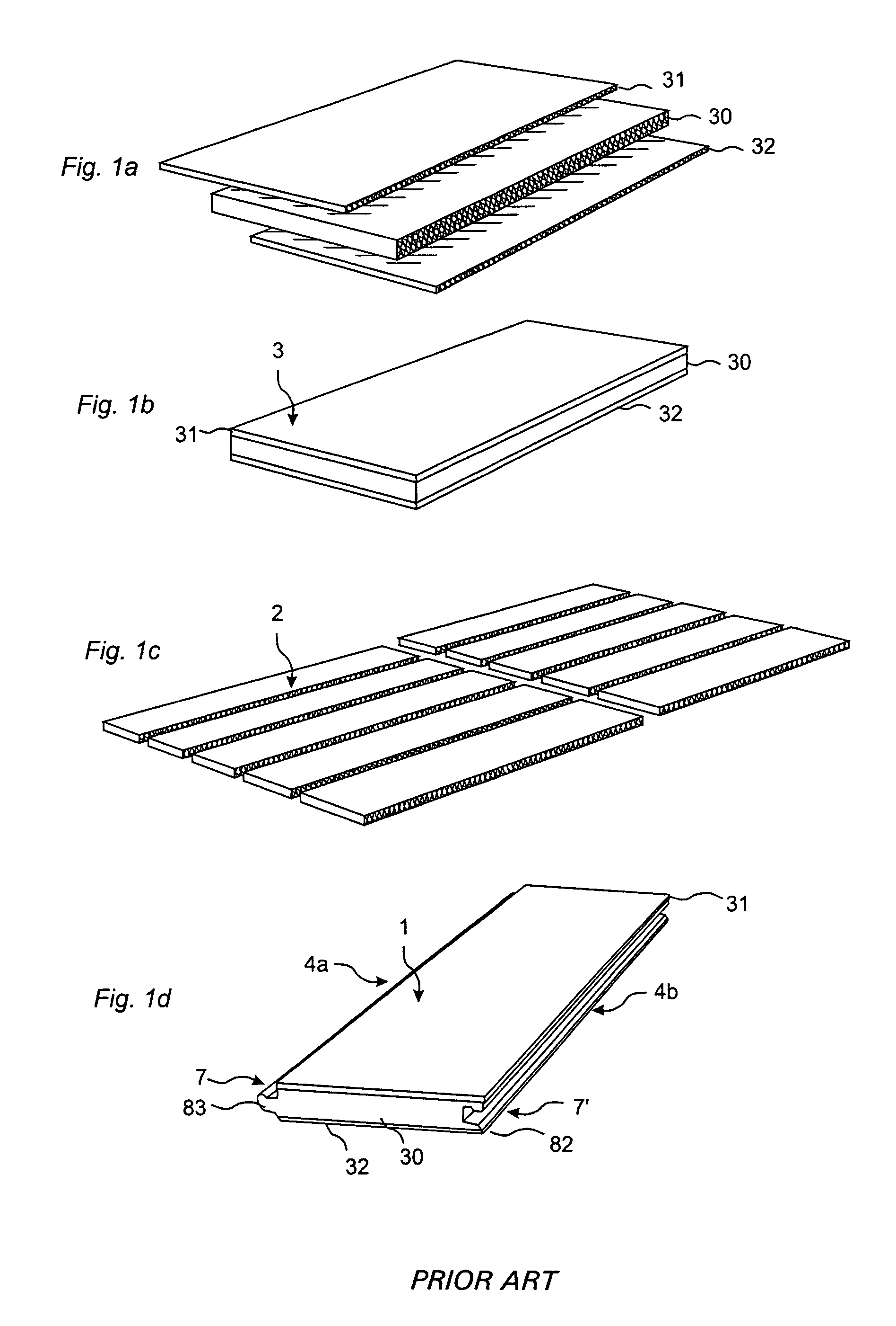
[0096]FIGS. 1a-d illustrate in four steps the manufacture of a floor panel. FIG. 1a shows the three main components surface layer 31, core 30 and balancing layer 32. FIG. 1b shows a floor element 3, where the surface layer and the balancing layer have been applied to the core. FIG. 1c shows how floorboards 2 are made by dividing the floor element. FIG. 1d shows how the floorboard 2 after edge machining obtains its final shape and becomes a completed floor panel 1 with a joint system 7, 7′ on the long sides 4a, 4b, which joint system in this case is mechanical.

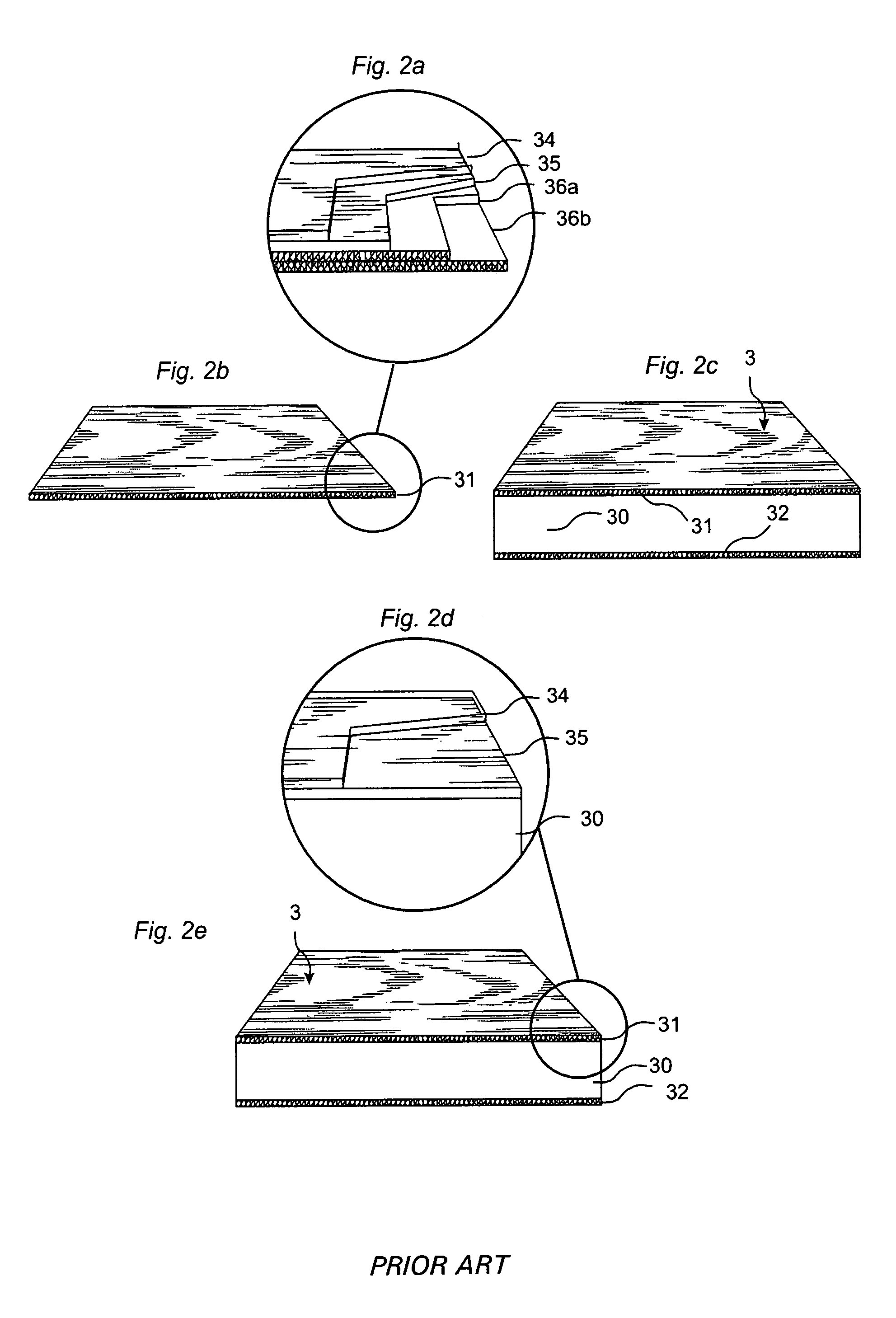
[0097]FIG. 2a shows manufacture of high pressure laminate. A wear layer 34 of a transparent material having a high wearing strength is impregnated with melamine with addition of aluminum oxide. A decorative layer 35 of paper impregnated with melamine is placed under this layer 34. One or more layers of reinforcement layers 36a, 36b made of paper core and impregnated with phenol are placed under the decorative layer 35, and the ...


PUM

PropertyMeasurementUnit
thickaaaaaaaaaa
speedsaaaaaaaaaa
thicknessaaaaaaaaaa

Abstract

Floor panels and floor elements therefore are made of sheet-shaped cores which before application of the surface of the floor panels are formed with sealing means for counteracting changes in the properties of the floor panels caused by moisture.

Description

[0001]This application claims priority under 35 U.S.C. §119(e) to U.S. Provisional Application No. 60 / 313,462 entitled FLOOR PANELS WITH SEALING MEANS and filed on Aug. 21, 2001, the entire content of which is hereby incorporated by reference.BACKGROUND[0002]1. Technical Field[0003]The invention relates generally to the field of moisture-proof joint systems for floor panels. The invention relates to a moisture-proof locking system for floor panels which can be joined mechanically; floor panels provided with such a locking system; semi-manufactures for producing such floor panels; and methods for producing such semi-manufactures and floor panels. Exemplary embodiments can be used in mechanical locking systems integrated with the floor panel, for instance, of the type described and shown in WO9426999, WO9966151, WO9966152, SE0100100-7 and SE0100101-5 (owner Välinge Aluminium AB) but is also usable in optional joint systems which can be used for joining of floors.[0004]More specificall...

Claims


Application Information

Patent Timeline
Patent Type & Authority Patents(United States)
IPC IPC(8): E04B1/00E04F15/02E04F15/04
CPCE04F15/02005E04F15/04E04F15/02038E04F15/02044E04F2201/0115E04F2201/0153E04F2201/026Y10T428/167E04F2201/049E04F2201/0517E04F2201/07E04F2201/042E04F15/02011E04F15/02016
Inventor PERVAN, DARKOPERVAN, TONY
Owner VÄLINGE INNOVATION AB
Why Eureka
Try Eureka